VAT 0750X-VE24 Retrofit-Ready Actuator for L-VAT Control Systems: Compatible Upgrade & Smooth Legacy System Migration
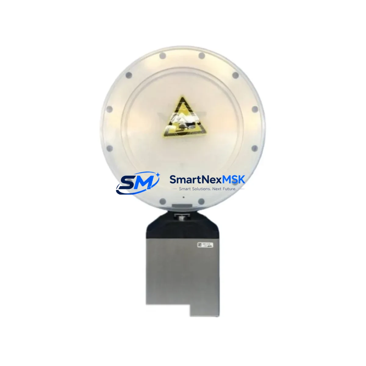
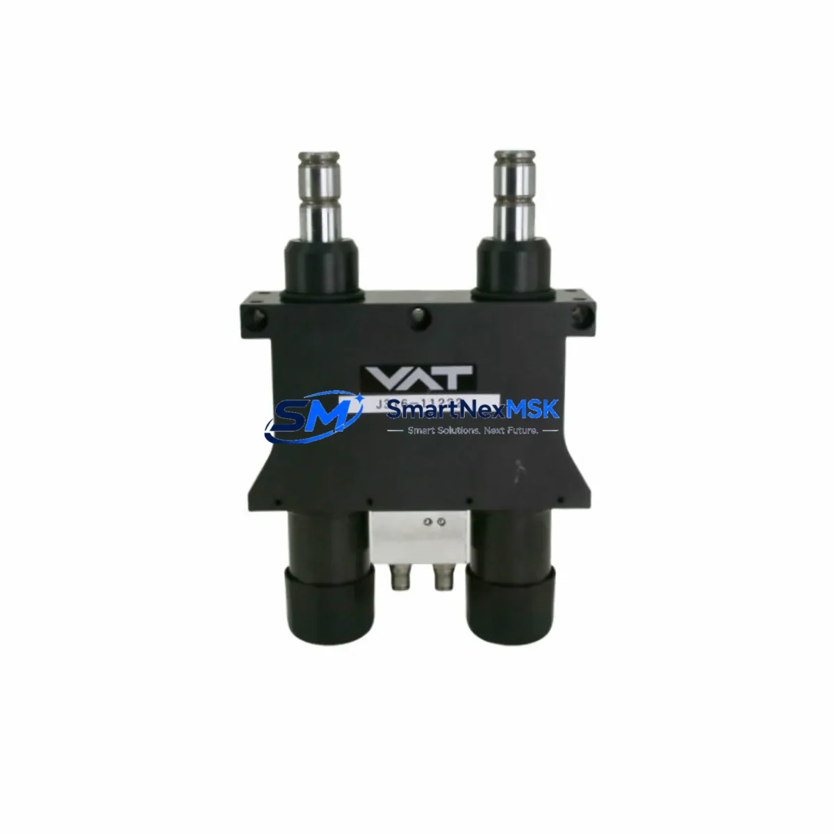
The VAT 0750X-VE24 (cross-reference: 949-608-00, LA608, C2148, P166/64, 8COM, 02-116798-00) is a precision pneumatic actuator engineered for the VAT L-VAT Series vacuum isolation valve platform. Widely deployed in semiconductor fabrication, thin-film deposition, flat-panel display manufacturing, and high-vacuum research environments, this actuator is the preferred retrofit solution for facilities managing aging valve assemblies, discontinued spare parts, or planned control system upgrades. SMARTNEXMSK maintains verified stock of the 0750X-VE24 with pre-shipment functional testing and a 12-month warranty on every unit shipped.
Whether you are replacing a failed actuator on an existing L-VAT gate valve body, upgrading from an earlier-generation VAT 0750 Series pneumatic drive, or migrating your process chamber isolation architecture to a more maintainable configuration, the 0750X-VE24 provides a mechanically and electrically compatible drop-in solution. The actuator interfaces directly with standard VAT valve bodies using the original mounting flange geometry, preserving your existing pneumatic supply lines, solenoid valve wiring, and position sensor feedback circuits without requiring panel modifications or custom adapters.
Upgrade Compatibility Table
| Parameter | Details |
|---|---|
| Primary SKU | VAT 0750X-VE24 |
| Cross-Reference / Alternate Part Numbers | 949-608-00 | LA608 | C2148 | P166/64 | 8COM | 02-116798-00 |
| Compatible Valve Series | VAT L-VAT Series (gate valve bodies, isolation valves) |
| Replaces / Upgrades From | VAT 0750 Series pneumatic actuators (earlier revisions); discontinued L-VAT actuator assemblies |
| Actuator Type | Pneumatic, double-acting or spring-return (confirm with valve body spec) |
| Supply Voltage (Solenoid) | 24 VDC (VE24 suffix) |
| Mounting Interface | Direct flange mount — matches original L-VAT body bolt pattern |
| Position Feedback | Integrated open/closed reed switch sensors; compatible with existing PLC digital input modules |
| Communication Compatibility | Hardwired I/O (24 VDC discrete); compatible with standard PLC DI/DO modules across major platforms |
| Installation Requirement | No valve body modification required; verify pneumatic supply pressure (typically 4–7 bar) |
| Commissioning Notes | Confirm solenoid polarity, sensor wiring color code, and PLC address mapping before power-on |
| Warranty | 12 Months — covers manufacturing defects; pre-shipment functional test included |
Retrofit Planning for Existing Automation Systems
Successful integration of the VAT 0750X-VE24 into a running production environment requires systematic pre-installation verification across several subsystems. Begin by auditing the pneumatic supply circuit: confirm that the compressed air or nitrogen supply to the valve actuator is regulated to the specified operating pressure range and that the upstream solenoid valve — typically a 24 VDC 4/2-way or 5/2-way unit from the existing control cabinet — is compatible with the 0750X-VE24 port sizing and flow coefficient. In many legacy installations, the solenoid valve itself (often a Festo MH series, SMC SY series, or equivalent) may also require replacement if it has accumulated significant cycle hours alongside the original actuator.
On the electrical side, the 0750X-VE24 solenoid coil operates at 24 VDC, consistent with the VE24 designation. Verify that the existing PLC digital output module — whether a Siemens S7-300 DO card, an Allen-Bradley 1756-OB16 ControlLogix output module, a Mitsubishi MELSEC QY series output unit, or an equivalent platform — can source sufficient current for the solenoid coil without exceeding the module’s per-channel current rating. In multi-valve control cabinets where several L-VAT actuators share a common 24 VDC power supply rail, recalculate the total inrush current budget when replacing multiple actuators simultaneously to avoid nuisance tripping of the cabinet’s 24 VDC power supply unit.
Position feedback from the 0750X-VE24 is provided by two reed switch sensors (open and closed position). These connect to the PLC’s digital input module — confirm terminal block wiring against the original as-built drawings, as sensor common and signal polarity conventions can vary between actuator revisions. If the existing installation uses a Siemens ET 200SP distributed I/O station or a Beckhoff EtherCAT I/O terminal block mounted in a remote field cabinet, verify that the sensor cable length and shielding are adequate for the installation distance. For systems using a Profibus DP or Profinet network backbone, no protocol changes are required — the 0750X-VE24 remains a hardwired device; only the PLC I/O mapping and HMI faceplate symbol assignments need to be confirmed.
If the process chamber uses a VAT 65040 or VAT 65048 Series pendulum valve in parallel with L-VAT isolation valves on the same vacuum line, ensure that the interlock logic in the PLC program correctly sequences the 0750X-VE24 actuator commands relative to the pendulum valve position to prevent simultaneous opening events that could compromise chamber pressure integrity. Similarly, if a MKS Instruments 651 Series pressure controller or an MKS 250E throttle valve controller governs downstream pressure, verify that the isolation valve open/close status signals feeding the pressure controller’s interlock inputs are correctly mapped after the actuator swap.
For facilities running older SCADA or DCS platforms — such as a Yokogawa CENTUM VP system, a Honeywell Experion PKS node, or an Emerson DeltaV controller — the actuator replacement itself does not require any DCS configuration changes beyond confirming that the field device tag assignment and I/O channel mapping in the DCS engineering database remain consistent with the physical wiring after the swap. Document all terminal block assignments, cable labels, and sensor addresses before beginning the physical replacement to enable rapid restoration if commissioning issues arise.
Downtime Control During System Migration
Minimizing unplanned downtime during an L-VAT actuator replacement requires a structured pre-maintenance preparation protocol. Before scheduling the replacement window, obtain a complete set of as-built electrical drawings for the control cabinet, the PLC program backup (including all rung comments and symbol table exports), and the HMI project file. For Siemens TIA Portal or STEP 7 environments, export the hardware configuration and I/O symbol table. For Rockwell Studio 5000 or RSLogix 5000 projects, create a verified offline backup and confirm the processor firmware version is documented.
During the replacement window, place the affected process chamber in a safe maintenance state using the PLC’s built-in maintenance mode or a dedicated bypass key switch if available. Do not rely solely on HMI-level inhibit commands — confirm at the PLC output module level that the solenoid output channel is de-energized before disconnecting the actuator wiring. After physical installation of the 0750X-VE24, perform a bench-level solenoid continuity check and sensor resistance verification before reconnecting to the control cabinet terminal block.
On power-up, command the valve through a full open-close-open cycle from the PLC’s manual jog function or a dedicated commissioning screen on the HMI panel. Verify that both the open and closed position feedback signals appear correctly in the PLC input image table and that the HMI faceplate updates the valve symbol state accurately. Confirm that all interlock conditions dependent on this valve’s position status — including chamber vent inhibits, pump start permissives, and process recipe step transitions — respond correctly before returning the chamber to automatic production mode. Total planned downtime for a single actuator swap, with adequate preparation, typically ranges from 2 to 4 hours including functional verification.
Retrofit Support FAQ
Q1: Is the VAT 0750X-VE24 a direct drop-in replacement for my existing L-VAT actuator?
In the majority of L-VAT Series installations, yes. The 0750X-VE24 shares the same mounting flange geometry, pneumatic port sizing, and 24 VDC solenoid specification as the standard L-VAT actuator assembly. Cross-reference your existing part number against the listed alternates (949-608-00, LA608, C2148, P166/64, 8COM, 02-116798-00) to confirm compatibility. If your existing actuator carries a different revision suffix, contact our technical team with the full nameplate data for confirmation before ordering.
Q2: What pre-shipment testing is performed on each unit?
Every VAT 0750X-VE24 unit shipped by SMARTNEXMSK undergoes a pre-shipment functional test that includes solenoid coil resistance measurement, pneumatic actuation cycle verification at rated supply pressure, and open/closed reed switch sensor output confirmation. A test record is available upon request. All units are covered by a 12-month warranty against manufacturing defects from the date of shipment.
Q3: Can I reuse my existing pneumatic tubing and solenoid valve during the actuator replacement?
In most cases, yes — provided the existing solenoid valve is in serviceable condition and the pneumatic tubing is free of contamination or moisture ingress. Inspect the solenoid valve coil resistance and verify that the valve body seals are not degraded before reusing. If the solenoid valve has accumulated more than 500,000 cycles or shows signs of leakage, replacement with a compatible 24 VDC unit is recommended to avoid a repeat maintenance event shortly after the actuator swap.
Q4: What documentation should I prepare before beginning the retrofit?
Prepare the following before starting: (1) as-built wiring diagram for the actuator terminal block connections; (2) PLC program backup with I/O symbol table; (3) HMI project backup; (4) pneumatic supply pressure specification for the valve; (5) current sensor wiring color code from the existing actuator nameplate or installation manual. Having this documentation ready reduces commissioning time and provides a recovery baseline if any unexpected behavior is observed during the post-installation functional test.
© 2026 SMARTNEXMSK. All rights reserved.
Original Source: https://smartnexmsk.com
Contact: sales@smartnexmsk.com | +86 18259474341