VICKERS EEA-PAM-513-A-32 Retrofit-Ready Proportional Amplifier for EEA-PAM Series Control Systems
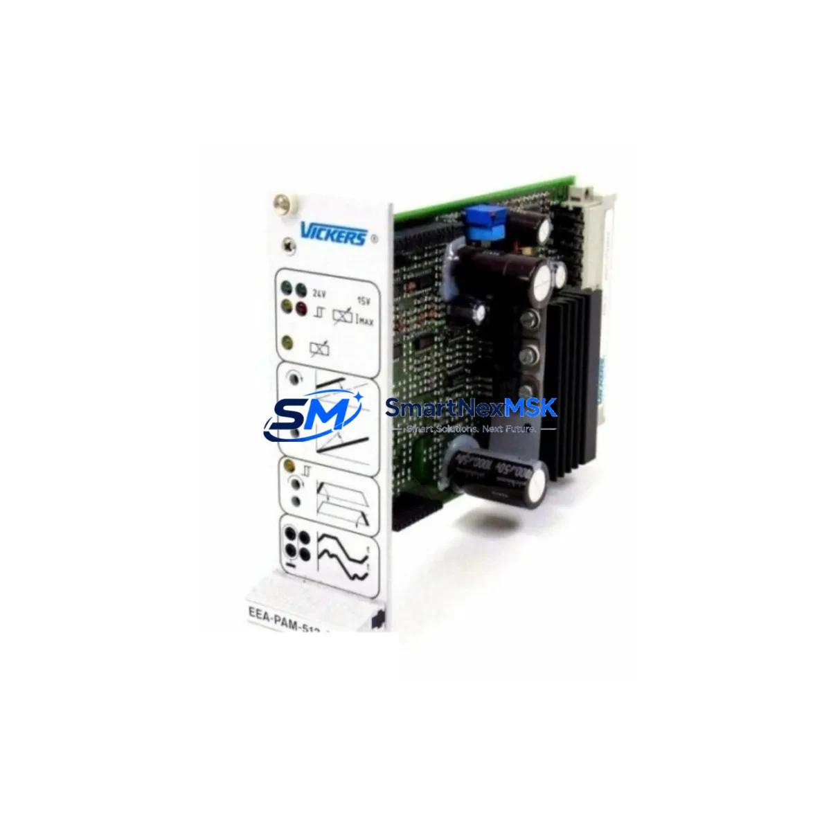
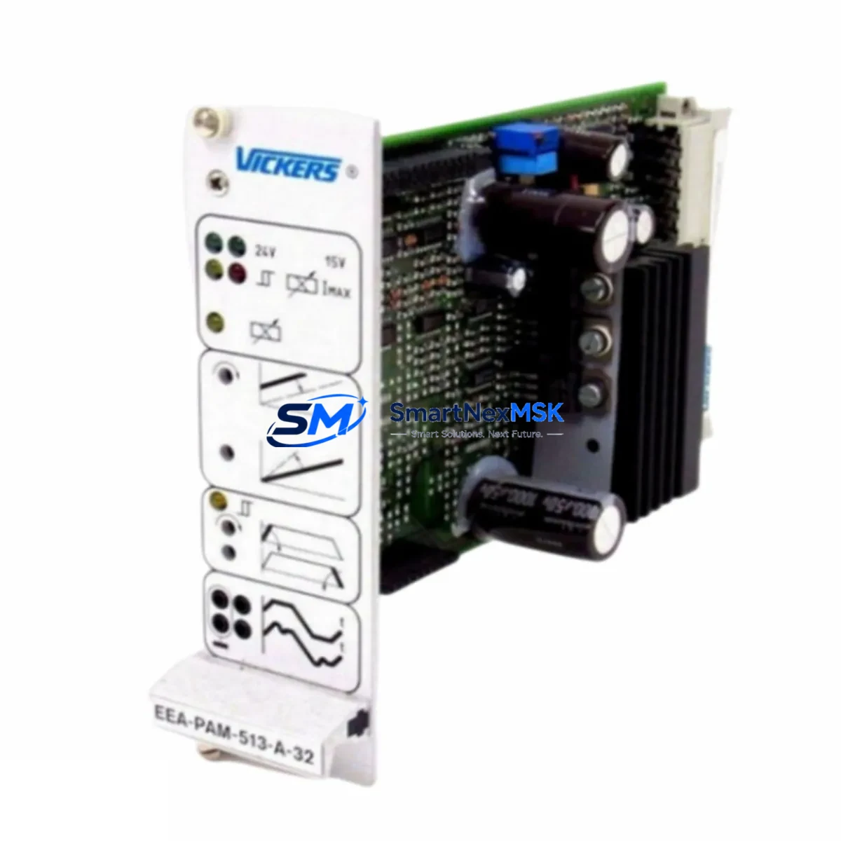
The VICKERS EEA-PAM-513-A-32 is a proportional amplifier card engineered for seamless integration into legacy hydraulic control systems built around the EEA-PAM Series platform. As original equipment reaches end-of-life and OEM support is discontinued, this module provides a verified retrofit path that preserves existing valve control logic, minimizes rewiring, and restores full closed-loop performance without requiring a complete system overhaul.
Industrial facilities operating VICKERS proportional directional control valves — including KDG4V, KDG5V, and KBFDG4V series — frequently rely on the EEA-PAM-513-A-32 as the signal conditioning and command interface between the PLC output and the valve solenoid driver stage. When this card fails or becomes unavailable through standard channels, the entire hydraulic axis can be rendered inoperable. Our stock of EEA-PAM-513-A-32 units is sourced, inspected, and function-tested to ensure drop-in compatibility with your existing panel wiring and DIN rail mounting arrangement.
Upgrade Compatibility Table
| Parameter | Details |
|---|---|
| Compatible Valve Series | VICKERS EEA-PAM Series (KDG4V, KDG5V, KBFDG4V and related proportional valves) |
| Mounting | DIN rail or panel mount; matches original EEA-PAM-513 footprint |
| Supply Voltage | 24 VDC nominal; verify existing PSU capacity before installation |
| Command Signal Input | ±10 VDC or 4–20 mA (confirm jumper configuration on existing card) |
| Communication Compatibility | Analog command interface; compatible with standard PLC analog output modules |
| Replacement Recommendation | Direct replacement for EEA-PAM-513-A-32; verify terminal block pinout against existing wiring diagram |
| Commissioning Notes | Ramp time, dither frequency, and gain potentiometers must be re-adjusted after swap |
| Warranty | 12-Month Warranty — covers functional defects under normal operating conditions |
Retrofit Planning for Existing Automation Systems
A successful EEA-PAM-513-A-32 retrofit begins well before the card arrives on site. Engineers should pull the original panel drawings and confirm the 24 VDC power supply — often a VICKERS or third-party DIN rail PSU — has sufficient current headroom to support the replacement card alongside any co-located I/O modules. In many legacy cabinets, the power budget was sized tightly around the original BOM, and adding a replacement card with slightly different inrush characteristics can trip upstream breakers if not accounted for.
Terminal block wiring is the next critical checkpoint. The EEA-PAM-513-A-32 uses a defined pinout for enable signal, command input, feedback, and solenoid output. Cross-reference the existing wiring against the card’s terminal diagram before disconnecting anything. In systems where the PLC analog output module — such as a Siemens SM 332 or Allen-Bradley 1756-OF8 — feeds the command signal, verify the output range is configured to match the card’s input mode (voltage or current loop).
Backplane and rack considerations apply if the amplifier card is housed within a modular enclosure alongside other VICKERS EEA-series modules. Confirm slot addressing and any address DIP switch settings match the original configuration. Systems that include a VICKERS EDICN or EDIC-series digital interface module for fieldbus communication — such as PROFIBUS-DP or DeviceNet — should have their node addresses and baud rate settings documented before the swap, as these parameters are not always retained in the PLC program.
For facilities running a Siemens S7-300 or S7-400 series PLC as the master controller, the analog output scaling in the hardware configuration (HW Config) must be verified to ensure the engineering unit range maps correctly to the ±10 VDC command range expected by the EEA-PAM-513-A-32. Similarly, if the system uses a Rockwell ControlLogix or CompactLogix controller, the AO channel scaling tag should be reviewed in Studio 5000 before live commissioning.
HMI faceplate screens — whether running on a Siemens TP700 Comfort, a Weintek MT8000 series, or a legacy VICKERS panel display — typically reference valve position feedback via analog input tags. After the card swap, verify that the feedback signal from the LVDT or pressure transducer connected to the valve is reading correctly on the HMI before releasing the axis to automatic mode. Communication links between the HMI and PLC (typically MPI, PROFINET, or Ethernet/IP) are unaffected by the amplifier card replacement but should be confirmed as stable before resuming production.
Downtime Control During System Migration
Minimizing unplanned downtime during an EEA-PAM-513-A-32 swap requires a structured pre-outage checklist. Before taking the hydraulic axis offline, export and archive the current PLC program — including all data blocks, function blocks, and symbol tables — to a secure backup location. This protects against accidental overwrite during any online edits performed during commissioning.
Where possible, schedule the card replacement during a planned maintenance window rather than responding reactively to a failure. Pre-stage the replacement EEA-PAM-513-A-32 alongside a calibrated signal generator and a multimeter so that bench verification of the card’s enable, command, and output functions can be completed before installation. This reduces in-cabinet troubleshooting time significantly.
During the physical swap, label all terminal connections before removal and photograph the existing wiring. Restore connections in reverse order of removal. After power-up, bring the axis into manual mode first and command a slow ramp to verify solenoid response before enabling closed-loop control. Adjust the ramp time and gain potentiometers incrementally, comparing valve response against the original commissioning records. Once the axis tracks correctly in manual, transfer to automatic and monitor for at least one full production cycle before signing off.
For systems where continuous operation is critical, consider maintaining a cold-standby EEA-PAM-513-A-32 in the spare parts cabinet. Given the discontinued status of this card through standard OEM channels, securing a second unit alongside the primary replacement is a prudent inventory strategy that eliminates future emergency sourcing delays.
Retrofit Support FAQ
Q: Is the EEA-PAM-513-A-32 a direct drop-in replacement for my existing card?
A: Yes, in the vast majority of EEA-PAM Series installations. The card matches the original terminal pinout, DIN rail mounting, and command signal interface. You should verify the command input mode (voltage vs. current) and re-adjust the onboard potentiometers (ramp, dither, gain) after installation, as these settings are not stored electronically.
Q: What commissioning steps are required after the card swap?
A: After physical installation and wiring verification, power up the card with the valve in a safe, unloaded state. Confirm the enable signal is present, then apply a low-level command signal and verify solenoid current output with a clamp meter. Adjust ramp time to match the original response profile, then proceed to closed-loop commissioning under PLC control. Document all final potentiometer positions for future reference.
Q: How do I confirm wiring compatibility before installation?
A: Obtain the terminal diagram for the EEA-PAM-513-A-32 and compare it pin-by-pin against your existing panel wiring. Pay particular attention to the enable input polarity, command signal ground reference, and solenoid output polarity. If the original card’s wiring diagram is unavailable, our technical team can assist with pinout identification based on your valve model and panel photos.
Q: What does the 12-month warranty cover?
A: The 12-month warranty covers functional defects in the EEA-PAM-513-A-32 under normal operating conditions, including failure to regulate solenoid current, loss of command signal response, or internal component failure. It does not cover damage resulting from incorrect wiring, overvoltage, or installation outside the card’s rated operating parameters. All units are function-tested prior to dispatch.
© 2026 SMARTNEXMSK. All rights reserved.
Original Source: https://smartnexmsk.com
Contact: sales@smartnexmsk.com | +86 18259474341