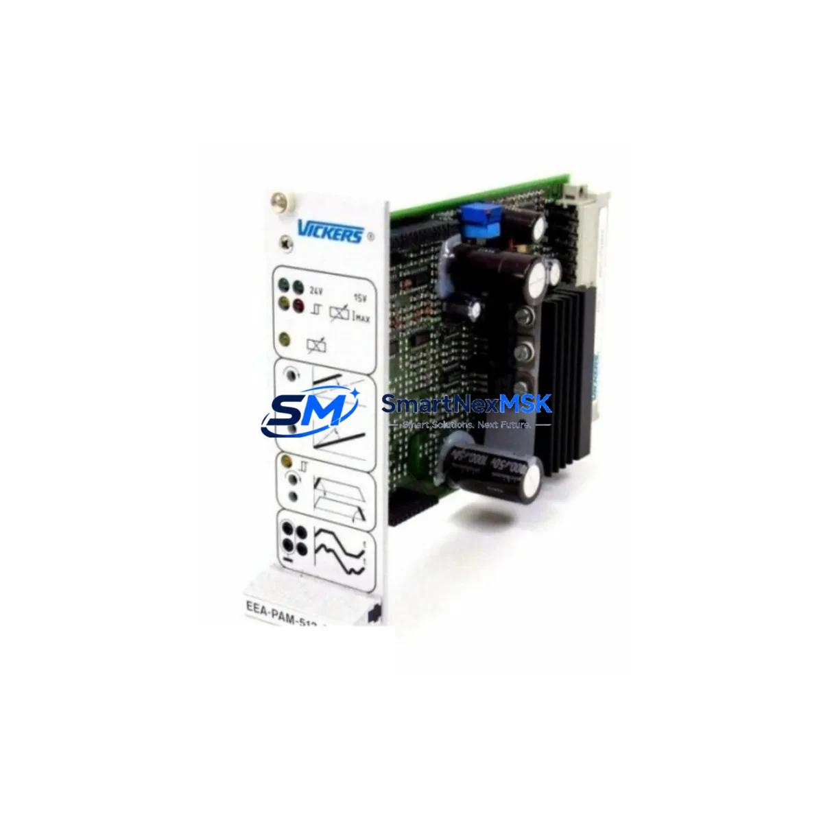
Vickers EEA-PAM-513-A32 02-326016 Spare for EEA-PAM Automation
The Vickers EEA-PAM-513-A32 02-326016 is an original proportional valve amplifier card engineered for precision electrohydraulic control in industrial automation systems. Designed for the EEA-PAM series, this amplifier card governs the electrical signal conditioning and output drive for proportional directional and pressure control valves — making it a mission-critical component in hydraulic servo loops, press control systems, injection molding machines, and continuous process lines.
When this card fails, the entire hydraulic axis loses closed-loop authority. Pressure overshoots, velocity drift, and uncontrolled actuator movement are immediate consequences. Downtime in these environments is measured in thousands of dollars per hour. Stocking a verified replacement EEA-PAM-513-A32 02-326016 is the single most effective hedge against unplanned outages in EEA-PAM-equipped control cabinets.
Every unit supplied by SMARTNEXMSK undergoes functional bench testing prior to shipment, is shipped with protective anti-static packaging, and is covered by a 12-month warranty against manufacturing defects. Long-term supply continuity is maintained for legacy EEA-PAM series installations, including systems that have been in service for 10–20 years.
Spare Maintenance Table
| Parameter | Specification |
|---|---|
| Part Number | EEA-PAM-513-A32 02-326016 |
| Brand | Vickers (Eaton Hydraulics) |
| Series | EEA-PAM (Proportional Amplifier Module) |
| Product Type | Proportional Valve Amplifier Card |
| Function | Signal conditioning & output drive for proportional valves |
| Supply Voltage | 24 VDC (nominal), ±15 VDC internal rails |
| Output Current | Up to 2.5 A (solenoid drive, proportional) |
| Input Signal | ±10 VDC analog command / enable signal |
| Compatibility | Vickers EEA-PAM series proportional valves; KFD, KHDG4, KBDG4 valve families |
| Mounting | DIN rail or panel-mount sub-base |
| Operating Temperature | 0 °C to +55 °C |
| Protection Class | IP20 (control cabinet installation) |
| Origin | Germany (OEM) |
| Condition | Original, new or reconditioned-to-spec |
| Pre-shipment Test | Functional bench test performed on every unit |
| Warranty | 12 Months |
| Lead Time | In stock — ships within 2 business days |
Maintenance Planning for Continuous Operation
Maintenance engineers replacing the EEA-PAM-513-A32 02-326016 should treat the event as a full electrohydraulic loop audit. The amplifier card does not fail in isolation — its failure is often precipitated or accompanied by degradation in adjacent components. A structured inspection of the following items is strongly recommended before returning the axis to service:
Power supply integrity: Verify the 24 VDC rail feeding the amplifier card using a calibrated multimeter. Ripple exceeding 200 mV peak-to-peak can corrupt the analog command signal and cause premature amplifier failure. If the cabinet uses a Vickers or third-party 24 VDC SMPS module, check its output under load and inspect the filter capacitors for bulging or leakage.
Analog command wiring and signal isolation: The ±10 VDC command signal from the PLC analog output module (AO card) must be shielded and grounded at one end only. Inspect the shielded cable run from the PLC I/O rack to the amplifier card terminal block. Ground loops introduced through improper shield termination are a leading cause of oscillation and valve hunting. Where signal integrity is suspect, a DIN-rail signal isolator (e.g., a 4–20 mA or ±10 VDC galvanic isolator) should be inserted in the command path.
Proportional valve solenoid coils: Measure the DC resistance of the proportional valve solenoid coils (typically 8–25 Ω depending on the valve model). A shorted or open coil will stress the amplifier output stage. For Vickers KHDG4 or KBDG4 series proportional valves, coil resistance should be within ±5% of the nameplate value.
Enable relay and interlock circuit: The EEA-PAM-513-A32 requires a clean enable signal. Inspect the enable relay — often a 24 VDC coil relay or solid-state relay — for contact wear, coil resistance drift, or delayed pull-in. A sluggish enable relay can cause the amplifier to receive a command before the enable is fully asserted, resulting in valve kick on startup.
PLC analog output module (AO card): Confirm the PLC AO channel driving the amplifier is within calibration. Use a precision voltage reference to verify the output at 0%, 50%, and 100% command. If the AO card is part of a Vickers-compatible PLC rack (e.g., Allen-Bradley, Siemens S7, or Mitsubishi Q-series), check for any active diagnostics on the channel.
Terminal blocks and connector integrity: Inspect all screw-terminal connections on the amplifier card sub-base and the adjacent terminal strip. Loose or oxidized terminals on the command, enable, feedback, and power connections are a frequent source of intermittent faults that are misdiagnosed as amplifier card failure.
Feedback transducer (LVDT or pressure transducer): If the hydraulic axis operates in closed-loop position or pressure control, verify the feedback transducer — LVDT, linear potentiometer, or pressure transducer — is within specification. A drifting feedback signal will cause the amplifier to command incorrect valve positions even after the card is replaced.
Cabinet thermal management: Confirm that cabinet ventilation fans, filter mats, and heat exchangers are clean and functional. The EEA-PAM-513-A32 is rated to +55 °C ambient. Cabinets running above this threshold will shorten amplifier card life significantly.
Site Replacement Workflow
Step 1 — Isolate and de-energize: Follow LOTO procedures. Isolate the 24 VDC supply to the amplifier card and confirm zero voltage at the card terminals before removal.
Step 2 — Document existing settings: Before removing the old EEA-PAM-513-A32 02-326016, photograph or record all potentiometer settings (ramp time, gain, dither frequency, current limit) visible on the card face. These settings are machine-specific and must be replicated on the replacement unit.
Step 3 — Remove and inspect: Extract the card from its sub-base or DIN rail mount. Inspect the PCB for burn marks, swollen capacitors, or damaged output transistors. Retain the failed card for root-cause analysis.
Step 4 — Install replacement: Seat the new EEA-PAM-513-A32 02-326016 firmly. Verify all connector pins are fully engaged. Torque terminal screws to specification (typically 0.5–0.6 N·m for M3 terminals).
Step 5 — Restore settings and power-up: Replicate the documented potentiometer settings. Apply 24 VDC and verify the enable LED illuminates. Issue a zero-command from the PLC and confirm the valve is at null position (no actuator drift).
Step 6 — Functional test: Ramp the command signal from 0% to 100% in controlled steps. Verify actuator response is smooth, proportional, and free of oscillation. Log the test results in the maintenance record.
Step 7 — Return to service: Remove LOTO, restore system to automatic mode, and monitor the first 30 minutes of operation for any anomalies.
This workflow minimizes re-work risk and ensures the replacement EEA-PAM-513-A32 02-326016 is commissioned correctly the first time, reducing total downtime to under two hours in most field scenarios.
Spare Parts Support FAQ
Q1: Is the EEA-PAM-513-A32 02-326016 still available as a new original part?
A: Yes. SMARTNEXMSK maintains long-term stock of original EEA-PAM-513-A32 02-326016 units to support legacy EEA-PAM series installations. All units are sourced from authorized channels and verified against OEM specifications before dispatch. We support systems that have been in service for 10–20 years and provide continuity of supply for obsolete or long-lead Vickers components.
Q2: How is compatibility with my existing EEA-PAM series valve confirmed before shipment?
A: Provide your full valve model number (e.g., KHDG4-3-250D-Z-M1-H1-10) and existing amplifier card part number when placing your order. Our technical team will cross-reference the valve’s solenoid specification, command signal type, and enable logic against the EEA-PAM-513-A32 02-326016 datasheet to confirm compatibility before the unit ships.
Q3: What does the 12-month warranty cover, and what is the claims process?
A: The 12-month warranty covers all manufacturing defects and functional failures under normal operating conditions. It does not cover damage caused by incorrect installation, overvoltage, or contamination. To initiate a warranty claim, contact sales@smartnexmsk.com with your order number, a description of the fault, and photos of the failed unit. Replacement units are dispatched within 3 business days of claim approval.
Q4: What is the recommended spare parts inventory strategy for EEA-PAM-equipped systems?
A: For systems with 1–3 EEA-PAM axes, we recommend holding one EEA-PAM-513-A32 02-326016 on the shelf at all times. For larger installations (4+ axes or 24/7 production), a minimum of two units is advisable. Pair the amplifier card spares with at least one set of proportional valve solenoid coils and a spare 24 VDC power supply module to cover the most common failure modes in a single maintenance event.
© 2026 SMARTNEXMSK. All rights reserved.
Original Source: https://smartnexmsk.com
Contact: sales@smartnexmsk.com | +86 18259474341