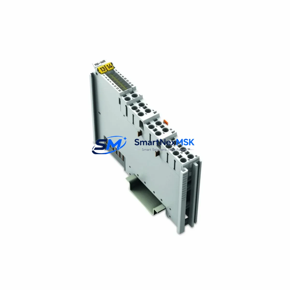
WAGO 750-1405 Maintenance-Ready Spare for 750 Series Automation
The WAGO 750-1405 is a 16-channel digital input module designed for the WAGO 750/753 Series modular I/O system. As a critical node in distributed control architectures, this module interfaces field-level sensors and switches directly to the PLC backplane, enabling real-time process monitoring across manufacturing, utilities, and infrastructure automation environments. Sourced as an original spare, the 750-1405 is tested prior to dispatch and backed by a 12-month warranty, making it a reliable choice for both planned maintenance and emergency downtime recovery.
For maintenance engineers managing aging WAGO 750 Series control cabinets, the 750-1405 represents one of the most frequently replaced I/O modules due to its exposure to field wiring faults, surge events, and long-term thermal cycling. Procurement engineers sourcing this module should verify compatibility with the active WAGO fieldbus coupler in use — whether a 750-303 PROFIBUS coupler, a 750-352 MODBUS TCP coupler, or a 750-362 DeviceNet coupler — as the fieldbus head determines the I/O mapping and diagnostic behavior of all downstream modules including the 750-1405.
When replacing the 750-1405 in the field, it is best practice to simultaneously inspect adjacent modules and shared infrastructure. The 24 VDC system power supply feeding the backplane — often a WAGO 787-series or equivalent DIN-rail PSU — should be load-tested to confirm it can sustain the full I/O module complement without voltage droop. Terminal blocks on the input wiring side, particularly WAGO 221-series or 2002-series lever-nut connectors, should be inspected for oxidation or loose terminations that may have caused the original module failure. If the cabinet includes a 750-627 or 750-628 potential distribution module, verify that the reference potential rails are intact and correctly bonded.
In systems where the 750-1405 shares a rack with analog input modules such as the 750-452 (4–20 mA, 2-channel) or 750-461 (PT100 RTD input), signal integrity should be confirmed after module swap. Noise coupling between digital and analog I/O sections is a known issue in dense 750 Series racks, and proper shielding of field cables at the cabinet entry gland plate is essential. If the system includes a 750-610 or 750-612 end module, confirm it is seated correctly after any module insertion or removal, as a missing or misaligned end module will prevent the coupler from initializing the I/O chain.
For facilities running predictive maintenance programs, the 750-1405 should be included in the annual control cabinet inspection checklist alongside the fieldbus coupler firmware version, the 24 VDC bus voltage measurement, and the status of any 750-series communication modules. Stocking one or two 750-1405 units as on-shelf spares is strongly recommended for any site with more than four WAGO 750 Series racks, given the module’s role in critical digital input acquisition and the lead times associated with sourcing original WAGO components through standard distribution channels.
All units supplied by SMARTNEXMSK are original, serialized, and subject to pre-shipment functional testing. Long-term supply continuity is supported for this model, and bulk procurement inquiries are welcome for MRO and system integrator customers.
Spare Maintenance Table
| Parameter | Specification |
|---|---|
| Part Number | 750-1405 |
| Brand | WAGO |
| Series | WAGO 750/753 Modular I/O |
| Module Type | 16-Channel Digital Input Module |
| Input Voltage | 24 VDC |
| Input Channels | 16 (IEC 61131-2 Type 1/3) |
| Signal Level (High) | 15–30 VDC |
| Signal Level (Low) | 0–5 VDC |
| Current Consumption | Approx. 70 mA (internal logic) |
| Isolation | Optical isolation, field side to backplane |
| Compatibility | WAGO 750/753 Series fieldbus couplers (PROFIBUS, MODBUS TCP, DeviceNet, EtherNet/IP) |
| Mounting | DIN rail, snap-on to WAGO 750 backplane |
| Operating Temperature | -25°C to +55°C |
| Protection Rating | IP20 |
| Origin | Germany |
| Warranty | 12 Months |
| Condition | Original, pre-shipment tested |
Maintenance Planning for Continuous Operation
A structured maintenance plan for any WAGO 750 Series installation should treat the 750-1405 as part of a broader I/O health review. During scheduled cabinet inspections, technicians should verify the operational status of the fieldbus coupler (e.g., 750-352 or 750-303), check the 24 VDC bus rail voltage at the power feed module, and confirm that all module status LEDs are green. The 750-1405’s per-channel input LEDs provide a fast visual diagnostic for field wiring continuity — any dark LED on a channel expected to be active warrants immediate investigation of the field device, cable, and terminal connection before condemning the module itself.
Adjacent modules that should be inspected during a 750-1405 replacement include: the 750-602 power supply module (if used for field-side power segmentation), any 750-series digital output modules sharing the same power segment, and signal conditioning components such as the 857-series signal isolators or 288-series surge protection terminals installed on the input wiring. If the system uses a 750-627 potential distribution module for common reference rails, its terminal integrity should be confirmed as part of the same maintenance event.
For sites with legacy WAGO 750 racks approaching end-of-life, a phased module refresh strategy — replacing I/O modules in order of failure frequency and criticality — can extend system life by 5–10 years without requiring a full PLC migration. The 750-1405 is a current-production module, ensuring long-term spare availability.
Site Replacement Workflow
- Power isolation: De-energize the field-side 24 VDC supply to the affected I/O segment. Do not remove the module under live field voltage.
- Documentation: Photograph or record the existing wiring connections and module slot position before removal.
- Module removal: Release the locking tab and slide the 750-1405 out of the backplane. Inspect the backplane connector for bent pins or contamination.
- Replacement insertion: Snap the new 750-1405 into the same slot. Confirm the module is fully seated and the locking tab is engaged.
- Wiring reconnection: Reconnect field wiring per the recorded documentation. Verify terminal torque on screw-type connections.
- Power restoration and verification: Re-energize the field supply and confirm all 16 channel LEDs reflect the expected field device states. Check the fieldbus coupler diagnostic display for any I/O configuration errors.
- PLC confirmation: From the PLC programming environment, verify that all 16 input bits mapped to the 750-1405 are reading correctly. Clear any latched fault bits in the coupler.
This workflow is compatible with hot-swap-capable WAGO coupler configurations where supported, but field-side de-energization is always recommended for safe replacement practice.
Spare Parts Support FAQ
Q: Is the WAGO 750-1405 compatible with all 750 Series fieldbus couplers?
A: Yes. The 750-1405 is compatible with all WAGO 750/753 Series fieldbus couplers, including PROFIBUS DP (750-303), MODBUS TCP (750-352), EtherNet/IP (750-354), and DeviceNet (750-362) variants. The module’s I/O mapping is determined by its slot position in the rack, which is read automatically by the coupler during initialization.
Q: What is the warranty coverage and how is it validated?
A: All 750-1405 units supplied by SMARTNEXMSK carry a 12-month warranty from the date of shipment. Each unit is serialized and undergoes pre-shipment functional testing. Warranty claims are supported by the original invoice and test record. Contact sales@smartnexmsk.com for warranty service.
Q: Can the 750-1405 replace older WAGO digital input modules such as the 750-400 or 750-1400?
A: The 750-1405 is the current-generation 16-channel digital input module and is the recommended replacement for legacy 8-channel and earlier 16-channel WAGO input modules. Slot mapping and PLC program I/O address assignments should be verified before substitution, as channel count differences may require configuration updates in the fieldbus coupler.
Q: What is the typical lead time and do you support bulk MRO orders?
A: In-stock units ship within 1–3 business days. For bulk MRO procurement or system integrator standing orders, contact sales@smartnexmsk.com or call +86 18259474341 to discuss pricing, lead time, and consignment stocking arrangements.
© 2026 SMARTNEXMSK. All rights reserved.
Original Source: https://smartnexmsk.com
Contact: sales@smartnexmsk.com | +86 18259474341