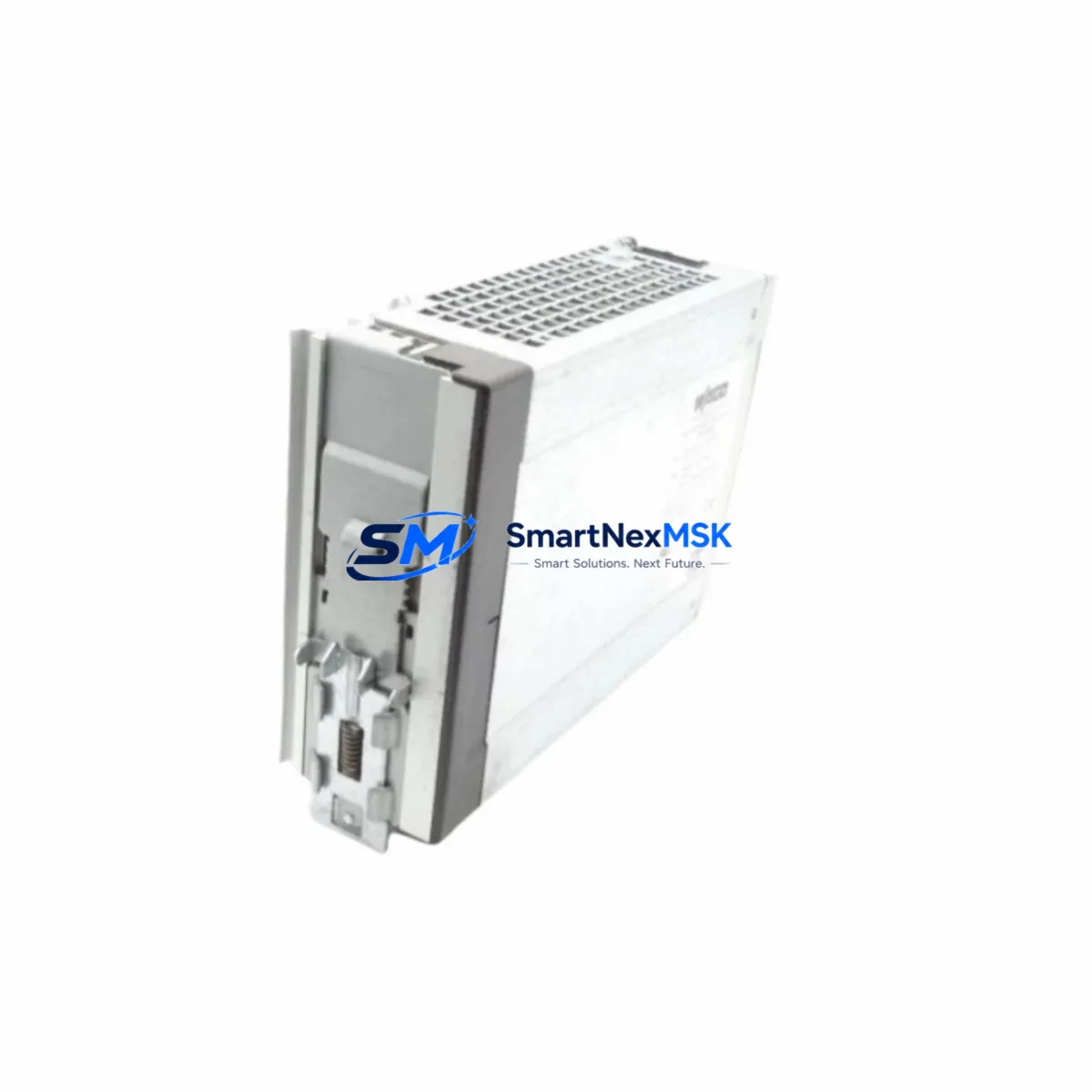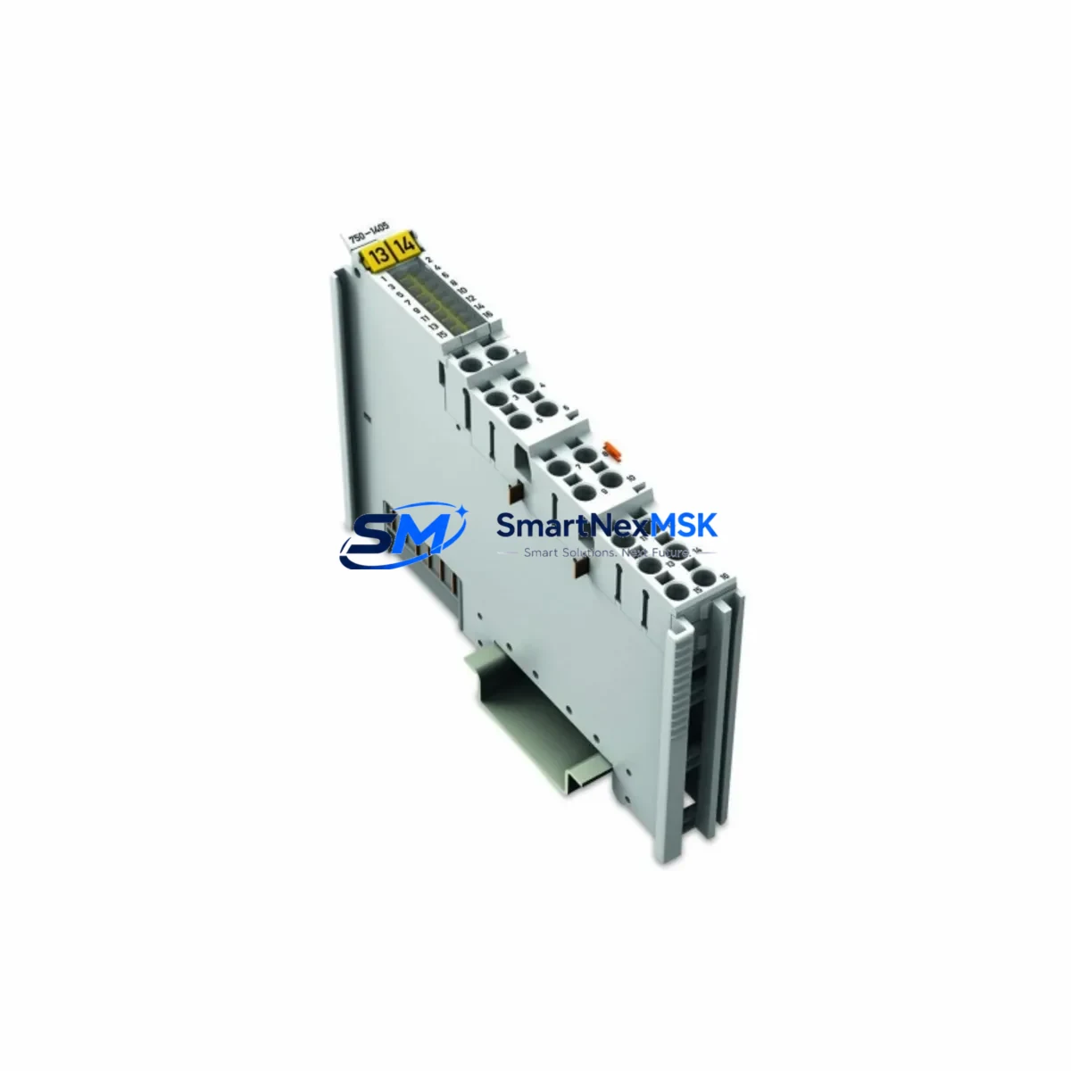
WAGO KL3454 Retrofit-Ready Thermocouple Input Module for 750 Series Control Systems
The WAGO KL3454 is a 4-channel thermocouple input module designed for seamless integration into WAGO 750 Series K-Bus fieldbus systems. As legacy automation infrastructure ages and original spare parts become increasingly difficult to source, the KL3454 serves as a verified retrofit solution for plants running older WAGO 750-series control architectures. Whether you are replacing a failed module in a running production line, upgrading a control cabinet to extend its operational life, or migrating from an end-of-life configuration, the KL3454 delivers the measurement accuracy and bus compatibility required for a smooth, low-risk transition.
This module supports Type K, J, B, E, N, R, S, and T thermocouples, providing broad sensor compatibility across furnace control, HVAC, food processing, and chemical plant applications. It connects directly to the K-Bus backplane without additional adapters, making it a drop-in replacement for systems already using WAGO 750-series terminal modules such as the 750-430 digital input module, 750-530 digital output module, or 750-504 relay output module installed in the same control cabinet.
Upgrade Compatibility Table
| Parameter | Detail |
|---|---|
| Module SKU | KL3454 |
| Brand / Series | WAGO / 750 Series K-Bus |
| Channels | 4 × Thermocouple Input |
| Supported TC Types | K, J, B, E, N, R, S, T |
| Bus Interface | K-Bus (WAGO 750 Series backplane) |
| Installation | DIN Rail, snap-on K-Bus connector, no tools required |
| Power Supply | 5 VDC via K-Bus (no external 24 VDC required for logic) |
| Communication Compatibility | Compatible with WAGO 750-841 (Modbus TCP), 750-352 (PROFIBUS DP), 750-315 (CANopen) couplers |
| Replacement Recommendation | Direct replacement for failed or discontinued 4-ch TC input modules in 750 Series racks |
| Commissioning Notes | Module address auto-assigned by coupler; verify channel mapping in WAGO-I/O-PRO or e!COCKPIT |
| Warranty | 12 Months from date of shipment |
| Origin | Germany |
Retrofit Planning for Existing Automation Systems
Integrating the KL3454 into an existing 750 Series control cabinet requires a structured pre-installation review. Begin by auditing the current rack configuration: identify the coupler head — typically a 750-841 Modbus TCP coupler or a 750-352 PROFIBUS DP coupler — and document the slot position of the module being replaced. The K-Bus backplane automatically enumerates modules from left to right, so inserting the KL3454 in the correct physical slot is critical to preserving the I/O address map used by the PLC program.
Check the power budget of the existing 750-602 or 750-610 power supply module. Each KL3454 draws approximately 70 mA from the K-Bus 5 VDC rail. If the rack is already near its current capacity — particularly in dense cabinets combining 750-430 digital input modules, 750-530 digital output modules, and 750-504 relay output modules — a supplementary 750-613 power supply terminal may be required before adding or replacing analog input modules.
Terminal wiring for the KL3454 follows the standard WAGO 750 Series spring-clamp connection method. Thermocouple leads connect directly to the module’s input terminals; polarity must be observed for each TC type. Cold junction compensation is handled internally, but verify that the ambient temperature inside the control cabinet is within the module’s rated operating range. If the existing installation used shielded TC extension cables, maintain the shield grounding scheme to avoid common-mode noise on the analog inputs.
For systems communicating over Modbus TCP via the 750-841 coupler, the KL3454 occupies a defined word address in the process image. After physical installation, update the Modbus register map in the SCADA or DCS host — such as a Siemens S7-300 acting as a Modbus master, or a Schneider Electric Modicon M340 in a mixed-vendor retrofit — to reflect the new channel assignments. If the plant uses an HMI panel such as a Weintek MT8000 or a Siemens TP700 Comfort, update the tag database to point to the correct register addresses before resuming production.
In PROFIBUS DP environments using the 750-352 coupler, the GSD file for the 750 Series rack must be re-imported into the engineering tool (STEP 7, TIA Portal, or Unity Pro) if the module count or type changes. Confirm that the DP slave address and baud rate settings on the coupler DIP switches remain unchanged during the swap to avoid bus communication faults.
Downtime Control During System Migration
Minimizing unplanned downtime is the primary concern during any live-system module replacement. Before removing the failed or obsolete module, export a full backup of the PLC program from the controller — whether a WAGO 750-8202 PFC200 or a third-party Modbus master — using WAGO-I/O-PRO or e!COCKPIT. Document the current process values on all active thermocouple channels so that post-installation readings can be validated against known baselines.
Where process conditions allow, schedule the physical swap during a planned maintenance window or shift changeover. The K-Bus hot-swap capability of the 750 Series means the coupler and remaining modules continue to operate during the swap, but the affected TC channels will report fault values until the new KL3454 is seated and the bus re-enumerates. Inform the DCS or SCADA operator to suppress alarms on the affected channels during the swap window to prevent spurious shutdowns.
After seating the KL3454, power-cycle the coupler to force a full K-Bus re-enumeration. Verify that the coupler’s diagnostic LEDs indicate normal operation and that all channel values are within expected ranges. Perform a point-to-point loop check on each thermocouple channel using a calibrated TC simulator before returning the system to automatic control. This pre-return verification step, combined with the module’s factory pre-shipment functional test, ensures that the 12-month warranty period begins from a confirmed operational baseline.
Retrofit Support FAQ
Q1: Is the KL3454 a direct drop-in replacement for my existing 4-channel thermocouple module in a 750 Series rack?
Yes. The KL3454 uses the standard K-Bus connector and DIN rail mounting shared by all 750 Series terminal modules. It occupies the same physical slot and is automatically recognized by the coupler during bus enumeration. No firmware update to the coupler is required in most cases; verify coupler firmware version compatibility if using a 750-841 with firmware below v02.06.
Q2: What commissioning steps are required after installing the KL3454?
After physical installation, power-cycle the coupler to trigger K-Bus re-enumeration. Open WAGO-I/O-PRO or e!COCKPIT and verify that the module appears in the correct slot position. Check the Modbus register map or PROFIBUS process image to confirm channel address alignment. Perform a TC simulator loop check on all four channels before returning to automatic mode. Update the HMI tag database if register addresses have shifted.
Q3: Can the KL3454 be used in a mixed-vendor control cabinet alongside Siemens or Schneider Electric components?
Yes. The KL3454 operates as a standard K-Bus I/O module under the WAGO 750 Series coupler. The coupler presents the process data to the fieldbus network (Modbus TCP, PROFIBUS DP, CANopen, etc.), making the thermocouple data accessible to any Modbus master or DP master regardless of brand. Siemens S7, Schneider Modicon, and Mitsubishi MELSEC controllers have all been used successfully as masters in mixed-vendor 750 Series installations.
Q4: What does the 12-month warranty cover, and how is it validated?
The 12-month warranty covers manufacturing defects and functional failures under normal operating conditions. Each unit undergoes a pre-shipment functional test verifying bus communication, channel accuracy, and cold junction compensation. Warranty claims require the original invoice and a description of the failure mode. Replacement or repair is provided at no charge within the warranty period. Contact sales@smartnexmsk.com with your order reference to initiate a warranty claim.
© 2026 SMARTNEXMSK. All rights reserved.
Original Source: https://smartnexmsk.com
Contact: sales@smartnexmsk.com | +86 18259474341