Bently Nevada 21000-34-05-00-030-03-02 Retrofit-Ready Proximity Probe for 21000 Series Control Systems
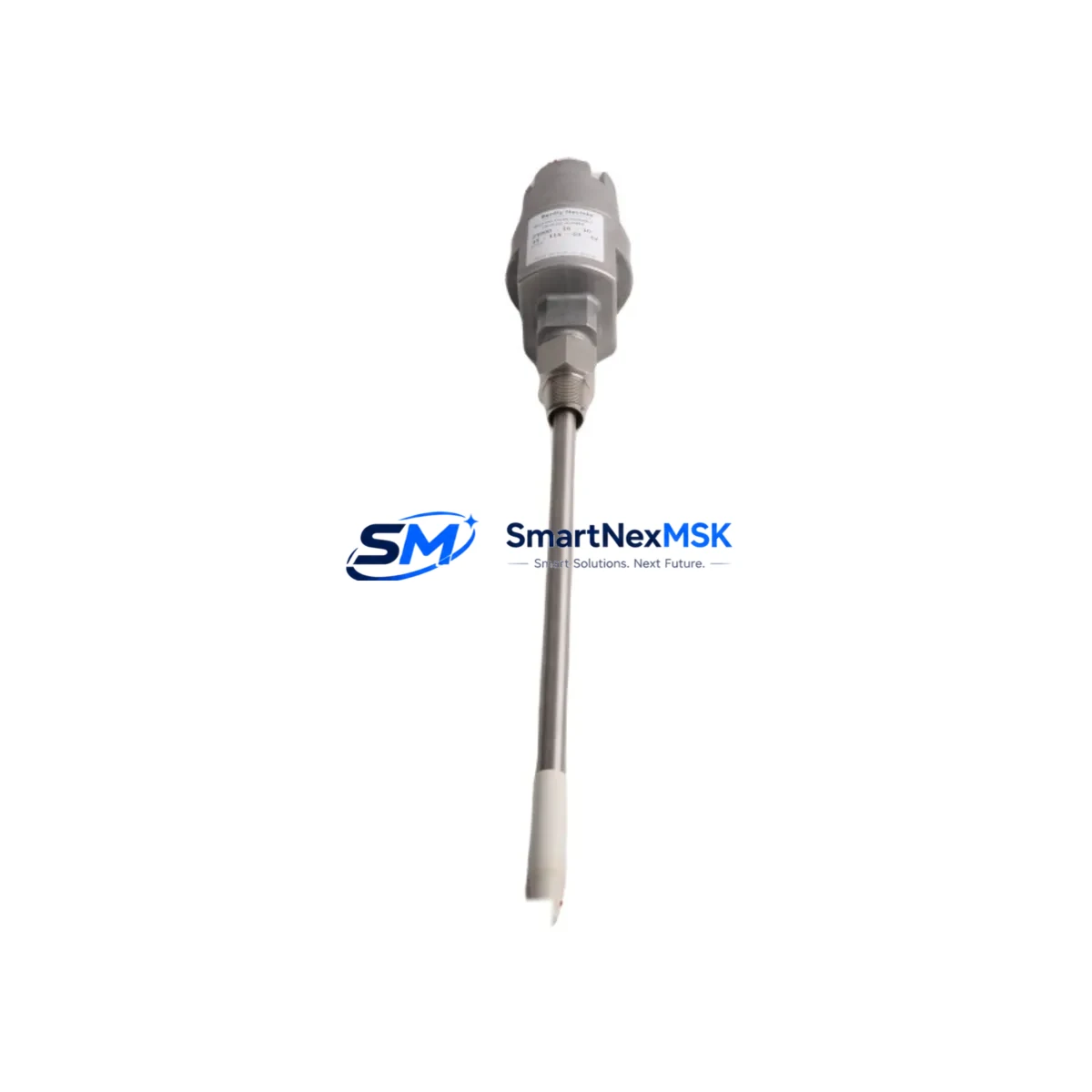
The Bently Nevada 21000-34-05-00-030-03-02 is a precision eddy-current proximity probe engineered for continuous vibration and position monitoring in rotating machinery applications. As legacy 21000 Series installations approach end-of-support milestones, this unit serves as a verified drop-in replacement and retrofit-ready upgrade for facilities managing turbines, compressors, pumps, and other critical rotating assets. Whether you are replacing a failed probe in an emergency shutdown scenario or executing a planned modernization of your condition monitoring infrastructure, this part delivers the dimensional accuracy, sensitivity, and signal integrity required for seamless integration into existing Bently Nevada 3300 Series monitor racks and Proximitor sensor assemblies.
The 21000-34-05-00-030-03-02 features a 25 mm probe tip diameter with a 300 mm armored extension cable and a standard 3-meter integral cable, making it directly interchangeable with the original factory specification. The probe operates within the standard Bently Nevada gap voltage range of -2 VDC to -18 VDC, ensuring full compatibility with paired Proximitor modules such as the 3300 XL 8mm Proximitor and the 3300 RAM Proximitor without requiring recalibration of the monitoring system. Engineers replacing probes in multi-channel monitor configurations should verify that the replacement probe’s sensitivity factor (mV/mil or mV/mm) matches the channel calibration stored in the 3500 Series rack or the System 1 condition monitoring software to avoid false alarm thresholds.
When retrofitting this probe into an existing installation, the following verification steps are critical: confirm the probe mounting thread (M10 x 1 standard), check the holddown nut torque specification, and verify the gap distance to the target shaft using a calibrated gap tool before energizing the channel. The armored cable routing should be inspected for any conduit damage or grounding faults that may have contributed to the original probe failure. In installations where the Proximitor extension cable (3300 XL Extension Cable or equivalent) has been in service for more than five years, replacement of the extension cable alongside the probe is strongly recommended to eliminate intermittent signal faults that can mask genuine machinery anomalies.
Upgrade Compatibility Table
| Parameter | 21000-34-05-00-030-03-02 (This Unit) | Notes / Retrofit Guidance |
|---|---|---|
| Probe Tip Diameter | 25 mm | Direct fit for standard 21000 Series mounting bosses |
| Integral Cable Length | 3 m (standard) | Verify conduit length before ordering extension cable |
| Extension Cable Compatibility | 3300 XL Extension Cable series | Replace extension cable if >5 years in service |
| Proximitor Compatibility | 3300 XL 8mm, 3300 RAM, 3500/42M | No recalibration required if sensitivity factor matches |
| Gap Voltage Range | -2 VDC to -18 VDC | Verify with System 1 or 3500 rack channel settings |
| Thread Specification | M10 x 1 | Use calibrated torque wrench; check holddown nut condition |
| Monitor Rack Compatibility | 3500 Series, 3300 Series | Confirm I/O module slot assignment before hot-swap |
| Communication Protocol | Analog (4–20 mA / voltage output) | No protocol migration required for direct replacement |
| Installation Requirement | Grounded armored cable, conduit routing | Inspect grounding continuity at junction box |
| Warranty | 12 Months | Covers manufacturing defects; includes pre-shipment bench test |
Retrofit Planning for Existing Automation Systems
Successful integration of the 21000-34-05-00-030-03-02 into a legacy condition monitoring system requires a structured approach that accounts for both the mechanical and electrical interfaces of the broader measurement chain. In a typical 3500 Series rack configuration, the probe signal passes through the Proximitor sensor, travels via the extension cable to the I/O module, and is processed by the 3500/42M Proximitor/Seismic Monitor card before being transmitted to the System 1 software platform or a DCS historian via Modbus TCP or OPC-DA. Any break in this signal chain — whether at the probe tip, the extension cable connector, the Proximitor housing, or the I/O terminal block — can result in a channel fault that triggers a machinery trip.
When planning a probe replacement during a scheduled outage, engineers should prepare the following components for concurrent inspection or replacement: the 3300 XL Extension Cable (or 3300 RAM Extension Cable for older installations), the Proximitor sensor housing and its mounting bracket, the terminal block wiring within the junction box, and the channel configuration record in the 3500 rack keypad or System 1 database. If the installation includes a 3500/20 Rack Interface Module for Ethernet connectivity, verify that the rack firmware version supports the probe sensitivity factor being used, as older firmware revisions may require a manual channel reset after probe replacement.
For facilities operating mixed-generation machinery protection systems — for example, a plant running both legacy 3300 Series monitors and newer 3500 Series racks on the same turbine train — the 21000-34-05-00-030-03-02 can serve both monitor generations without modification, provided the Proximitor model is matched correctly. In such environments, it is common to find 3300/16 Dual Voting Logic modules or 3300/55 Temperature Monitor cards installed in adjacent rack slots; these modules are unaffected by probe replacement but should be visually inspected for terminal corrosion during the same maintenance window. Similarly, if the control system includes a 3500/61 FOUNDATION Fieldbus I/O Module or a 3500/92 Communication Gateway for integration with a DCS such as Honeywell Experion or Emerson DeltaV, the gateway configuration should be reviewed to confirm that the probe channel tag mapping remains intact after the replacement.
Downtime Control During System Migration
Minimizing unplanned downtime during a proximity probe replacement requires pre-staging all replacement components, completing the gap calibration procedure offline, and coordinating the channel bypass sequence with the control room operator before breaking the probe connection. For critical machinery protected by a 3500 Series rack in trip-enabled mode, the affected channel should be placed in bypass using the rack keypad or System 1 software before the probe is disconnected. This prevents a spurious trip signal from propagating to the machinery protection relay and causing an unplanned shutdown of the turbine or compressor train.
Once the replacement 21000-34-05-00-030-03-02 is installed and the gap is set to the manufacturer-specified nominal value (typically 1.0 mm to 1.5 mm for a 25 mm probe on a steel target), the channel should be brought out of bypass in a controlled sequence: first verify the gap voltage reading at the Proximitor output terminals, then confirm the vibration reading in System 1 or the rack display matches the expected baseline for the machine at rest, and finally re-enable the trip function only after the machine has been restarted and the vibration signature has stabilized. This sequence protects the original program logic stored in the 3500 rack and preserves the alarm and trip setpoints configured for the specific machine train, eliminating the need for a full system recommissioning after a routine probe replacement.
All units are pre-shipment bench-tested against Bently Nevada factory specifications and supplied with a 12-month warranty covering manufacturing defects. In-stock inventory ensures same-week dispatch for urgent replacement requirements, supporting maintenance teams that need to minimize the window between machinery shutdown and return-to-service.
Retrofit Support FAQ
Q: Is the 21000-34-05-00-030-03-02 a direct drop-in replacement for the original Bently Nevada part?
A: Yes. This unit is manufactured to the original dimensional and electrical specification, including probe tip diameter, thread pitch, cable length, and sensitivity factor. It is compatible with the 3300 XL 8mm Proximitor, 3300 RAM Proximitor, and 3500/42M monitor card without requiring recalibration, provided the gap is set correctly during installation.
Q: What gap setting should I use during installation?
A: The nominal gap for a 25 mm eddy-current probe on a steel target shaft is typically 1.0 mm to 1.5 mm, corresponding to a Proximitor output voltage of approximately -10 VDC at center gap. Verify the exact gap specification against the machine OEM documentation and the channel calibration record in your 3500 rack or System 1 database before finalizing the installation.
Q: Can this probe be used with a 3500 Series rack running Modbus TCP communication to a DCS?
A: Yes. The probe itself is an analog sensor; the communication protocol is handled by the 3500 rack’s gateway module (such as the 3500/92 Communication Gateway). Replacing the probe does not affect the Modbus TCP configuration or the tag mapping in the DCS historian. After replacement, verify that the channel is reporting correctly in the DCS faceplate before closing the maintenance work order.
Q: What does the 12-month warranty cover?
A: The warranty covers manufacturing defects in materials and workmanship for 12 months from the date of shipment. Each unit undergoes a pre-shipment bench test to verify electrical continuity, sensitivity factor, and cable integrity. Warranty claims are processed with priority dispatch of a replacement unit to minimize machinery downtime.
© 2026 SMARTNEXMSK. All rights reserved.
Original Source: https://smartnexmsk.com
Contact: sales@smartnexmsk.com | +86 18259474341


