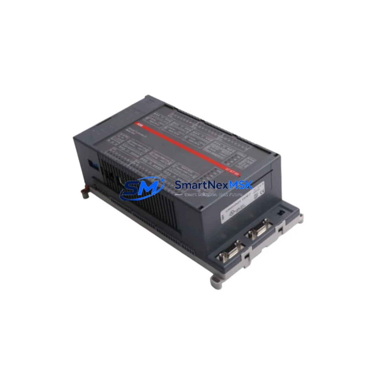
ABB 07KT98 GJR5253100R0270 Retrofit-Ready CPU for AC31 Control Systems
The ABB 07KT98 (part number GJR5253100R0270) is a central processing unit module designed for the ABB AC31 programmable logic controller series. As AC31 platforms approach end-of-life and original spare parts become increasingly scarce, the 07KT98 remains one of the most sought-after retrofit and replacement components for engineers tasked with sustaining legacy production lines, upgrading aging control cabinets, and migrating automation architectures to modern communication standards — all while minimizing unplanned downtime.
Whether you are replacing a failed CPU in a running plant, consolidating a multi-rack AC31 installation, or executing a phased migration toward an AC500 platform, the 07KT98 provides the processing backbone that keeps your control system operational. Its compatibility with the AC31 backplane and I/O bus means that existing terminal wiring, field devices, and cabinet layouts can be preserved during the swap, dramatically reducing the engineering hours and commissioning risk associated with a full system replacement.
Upgrade Compatibility Table
| Parameter | Details |
|---|---|
| Model / SKU | ABB 07KT98 / GJR5253100R0270 |
| Series Compatibility | ABB AC31 (07KT series) |
| Backplane / Rack Interface | AC31 standard backplane bus; compatible with 07CR41, 07CR91 racks |
| Communication Protocols | PROFIBUS-DP, CS31 bus, serial RS-232/RS-485 |
| I/O Expansion | Supports AC31 digital and analog I/O modules via CS31 bus |
| Power Supply Requirement | 24 V DC via backplane; verify existing 07PS60 or 07PS90 power supply capacity before swap |
| Program Memory | Compatible with existing AC31 application programs; verify compiler version before reload |
| HMI Compatibility | Compatible with CP600 and legacy Panel Builder HMI screens via serial link |
| Replacement Recommendation | Direct replacement for 07KT97, 07KT94; phased upgrade path toward AC500 PM573/PM583 |
| Commissioning Focus | Module address DIP switch setting, CS31 node address, program upload/download via 07SK90 cable |
| Warranty | 12-Month Warranty — tested and verified before shipment |
Retrofit Planning for Existing Automation Systems
A successful 07KT98 retrofit begins well before the module arrives on site. The first step is a thorough audit of the existing AC31 rack configuration. Identify the current CPU slot position within the 07CR41 or 07CR91 rack, document all occupied I/O slots — including any 07DI90 digital input modules, 07DO90 digital output modules, and 07AI90 analog input modules — and photograph the existing terminal wiring before any disconnection takes place.
Power supply capacity is a critical pre-check. The 07PS60 or 07PS90 power supply module must be verified to deliver sufficient 24 V DC current for the 07KT98 plus all connected I/O modules. If the existing power supply is operating near its rated output, consider upgrading to a higher-capacity unit during the same maintenance window to avoid a secondary failure shortly after the CPU swap.
Communication wiring deserves equal attention. If the installation uses a CS31 bus to connect remote I/O nodes — such as 07KR91 remote I/O couplers or distributed terminal modules — verify that the bus termination resistors are correctly installed at both ends of the cable run. PROFIBUS-DP segments connected to the 07KT98 should be checked for correct baud rate settings and node addresses before the new CPU is powered up. Where RS-232 or RS-485 serial links connect to a CP600 HMI panel or a SCADA gateway, confirm that the communication parameters (baud rate, parity, stop bits) match the settings stored in the replacement CPU’s configuration.
Module addressing is another area where errors commonly occur during AC31 CPU replacements. The 07KT98 uses DIP switches on the module face to set the rack address and CPU slot assignment. These must be configured to match the original module’s settings before insertion into the backplane. Failure to do so will cause the CPU to fail its self-test and prevent the control program from loading. Keep the original module’s DIP switch photograph as a reference throughout the commissioning process.
Program compatibility should be confirmed by retrieving the original application from the plant’s backup archive or by uploading it directly from the old CPU using a 07SK90 programming cable before the swap. Verify the program version against the AC31 compiler release notes to ensure it will execute correctly on the replacement 07KT98 firmware. If the program was compiled under an older toolset, a recompile under the current 907 AC 1131 engineering software version may be required.
Downtime Control During System Migration
Minimizing production downtime during an AC31 CPU replacement requires a structured hot-swap preparation protocol. Begin by scheduling the replacement during a planned maintenance window rather than responding reactively to a failure. Pre-configure the replacement 07KT98 off-line: set the DIP switches, load the verified application program, and confirm the module passes its internal diagnostics before bringing it to the machine.
During the physical swap, follow a strict sequence: power down the rack via the 07PS60 or 07PS90 supply, remove the failed CPU, insert the pre-configured 07KT98, and restore power. Do not attempt a hot insertion on a live backplane. Once power is restored, monitor the CPU status LEDs through the startup sequence — RUN, STOP, and ERROR indicators will confirm whether the program has loaded and the CS31 bus has initialized correctly.
If the installation includes a CP600 HMI panel, verify that the HMI communication link re-establishes automatically after the CPU restart. In most AC31 installations, the HMI will reconnect within 30 seconds of the CPU entering RUN mode. If the HMI displays a communication fault, check the serial cable connection and confirm that the CPU’s communication port parameters have been correctly restored from the program backup.
For installations where continuous process control is critical, consider deploying a temporary bypass using hardwired relay logic to maintain essential outputs during the CPU swap window. This approach is particularly valuable in applications such as pump control, conveyor sequencing, or HVAC management where even a brief interruption in output signals can trigger downstream process upsets. Document the bypass configuration and remove it completely before returning the system to automatic control.
Retrofit Support FAQ
Q1: Is the ABB 07KT98 GJR5253100R0270 a direct drop-in replacement for the 07KT97?
Yes. The 07KT98 is mechanically and electrically compatible with the same AC31 backplane slots used by the 07KT97 and 07KT94. The DIP switch configuration must be replicated from the original module, and the application program should be reloaded from a verified backup. No wiring changes to the rack or I/O modules are required in a standard like-for-like swap.
Q2: What programming cable and software are required to upload and download programs to the 07KT98?
The 07KT98 uses the 07SK90 serial programming cable connected to the CPU’s front-panel RS-232 port. Programming is performed using ABB’s 907 AC 1131 engineering software. Ensure the PC’s COM port settings match the CPU’s default communication parameters (typically 19200 baud, 8N1) before initiating the connection.
Q3: How do I verify wiring and I/O compatibility before powering up the replacement module?
Before powering up, confirm that all CS31 bus cables are correctly terminated, all I/O module addresses are set to their original values, and the 24 V DC supply voltage at the backplane connector is within the specified tolerance (typically 20.4–28.8 V DC). Use a multimeter to verify supply voltage at the 07PS60 or 07PS90 output terminals before inserting the 07KT98. After power-up, use the 907 AC 1131 software to perform an online I/O force test to confirm all digital and analog channels are responding correctly.
Q4: What does the 12-month warranty cover, and how is the module tested before shipment?
Every 07KT98 GJR5253100R0270 unit supplied by SMARTNEXMSK undergoes functional testing prior to shipment, including power-on self-test verification, communication port checks, and program load/run confirmation. The 12-month warranty covers manufacturing defects and functional failures under normal operating conditions. Units are shipped with protective packaging to prevent ESD damage during transit. In the event of a warranty claim, contact sales@smartnexmsk.com with your order reference and a description of the fault observed.
© 2026 SMARTNEXMSK. All rights reserved.
Original Source: https://smartnexmsk.com
Contact: sales@smartnexmsk.com | +86 18259474341


