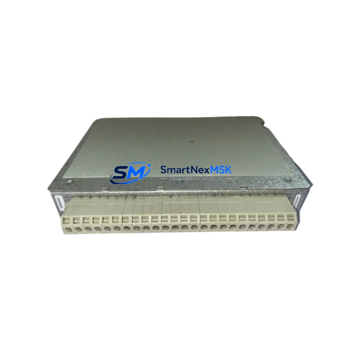
ABB 1MRK002247-ARr01 Retrofit-Ready TRM for RET Series Control Systems
The ABB 1MRK002247-ARr01 is a Transformer Monitoring Module (TRM) engineered for seamless integration into ABB RET series protection relay platforms. Designed as a retrofit-ready replacement, this module addresses the growing demand for reliable spare parts and upgrade components in aging substation automation and transformer protection systems. Whether you are replacing a failed unit, upgrading a legacy RET 521 or RET 670 installation, or migrating from an older REF or REB series architecture, the 1MRK002247-ARr01 provides a verified drop-in solution with full backward compatibility across supported firmware revisions.
Industrial facilities operating ABB’s Relion® 670 series or earlier RET platform installations frequently encounter obsolescence challenges as original modules reach end-of-life. The 1MRK002247-ARr01 TRM is stocked specifically to support these retrofit scenarios, offering procurement teams and maintenance engineers a dependable source for critical protection relay components without the lead times associated with factory orders. Each unit undergoes pre-shipment functional testing and ships with a 12-month warranty covering manufacturing defects and operational failures under normal service conditions.
Upgrade Compatibility Table
| Parameter | Details |
|---|---|
| Compatible Platform | ABB RET Series (RET 521, RET 670, RET 650) |
| Module Type | Transformer Monitoring Module (TRM) |
| Backplane Interface | Standard RET series module slot; verify slot position against station configuration tool (SCT) project file |
| Communication Protocol | IEC 61850 Edition 1 & 2; GOOSE messaging supported |
| Installation Requirement | DIN rail or 19″ rack mount per existing RET chassis; no mechanical modification required |
| Terminal Wiring | Confirm CT/VT secondary wiring against original terminal diagram; polarity and grounding must be verified before energization |
| Firmware Compatibility | Verify relay firmware version via PCM 600 before module swap; update if required |
| Replacement Recommendation | Direct replacement for failed or end-of-life TRM in RET 521/670/650 installations |
| Commissioning Note | Re-download application configuration via PCM 600 after module replacement; validate protection settings and GOOSE subscriptions |
| Warranty | 12 months from date of shipment; covers manufacturing defects and operational failures under normal service conditions |
Retrofit Planning for Existing Automation Systems
Successful retrofit of the ABB 1MRK002247-ARr01 into an operating substation or industrial control environment requires systematic pre-installation planning. Engineers should begin by auditing the existing RET relay chassis to confirm available module slots, backplane revision, and current firmware version using ABB’s PCM 600 engineering tool. The module address assignment must be verified against the active station configuration tool (SCT) project to avoid address conflicts with adjacent modules such as the BIM (Binary Input Module), BOM (Binary Output Module), or IOM (Input/Output Module) already installed in the same chassis.
Power budget verification is a critical step often overlooked during module replacement. The RET series chassis power supply — typically a PSM (Power Supply Module) rated for the installed module count — must have sufficient headroom to support the 1MRK002247-ARr01 alongside existing modules. If the installation includes a GPS time synchronization module or an additional communication module such as the SLM (Serial Link Module) for legacy MODBUS or DNP3 connectivity, the total chassis power draw must be recalculated before the new TRM is inserted.
Terminal wiring adaptation is another key consideration. The CT and VT secondary circuits feeding the TRM must be isolated, shorted, and verified for correct polarity before the old module is removed. Wiring diagrams from the original RET 521 or RET 670 installation should be cross-referenced against the 1MRK002247-ARr01 terminal assignment to confirm that differential protection inputs, restricted earth fault (REF) circuits, and thermal overload monitoring channels are correctly mapped. Where the original installation used a REX 521 or REF 615 in a mixed protection scheme, the interface between the TRM and the overall protection coordination logic must be re-validated.
For sites migrating from older ABB SPACOM or PYRAMID series protection systems to the RET platform, the 1MRK002247-ARr01 serves as the transformer monitoring anchor point in the new architecture. In these migration projects, the HMI screen layouts in the local operator panel (LOP) or remote SCADA system will require updating to reflect the new module’s data model and IEC 61850 logical node structure. GOOSE message subscriptions between the TRM and associated bay controllers or interlocking logic must be re-configured and tested under simulated fault conditions before the protection system is returned to service.
Sites that include ABB REC 670 bay controllers, REL 670 line protection relays, or REB 670 busbar protection units in the same substation automation system (SAS) should plan for a coordinated commissioning sequence. The 1MRK002247-ARr01 TRM’s GOOSE outputs feeding trip commands to circuit breaker control modules must be verified end-to-end, including the optical fiber or copper Ethernet links connecting the relay to the station bus switch.
Downtime Control During System Migration
Minimizing unplanned outage duration during TRM replacement is a primary concern for operations teams managing live transformer bays. The recommended approach is to prepare a complete offline backup of the PCM 600 application configuration before any hardware is disturbed. This backup preserves all protection settings, parameter groups, disturbance recorder configurations, and GOOSE subscription tables, allowing the engineering team to restore the full application to the replacement 1MRK002247-ARr01 within minutes of physical installation.
Where a planned maintenance window is available, a staged replacement strategy reduces risk. The new TRM can be pre-configured and tested on a bench setup using a PCM 600 offline project before the maintenance window opens. During the window, the existing module is de-energized, CT circuits are shorted, wiring is transferred, and the pre-configured replacement is inserted. The PCM 600 application download is then executed, protection settings are verified against the approved relay setting sheet, and GOOSE communication is confirmed active before CT shorts are removed and the transformer bay is returned to service.
For sites without a planned outage window, a hot-standby approach using a parallel protection scheme — where a second RET relay or a REF 615 feeder protection relay provides backup coverage during the TRM swap — can maintain protection continuity throughout the replacement process. This approach requires advance coordination with the system operator and documentation of the temporary protection arrangement in the site’s maintenance management system.
Post-replacement, a full functional test sequence should be executed: inject test currents via a relay test set to verify differential protection pickup, check thermal model initialization, confirm disturbance recorder trigger thresholds, and validate remote SCADA visibility of all TRM status points. Only after successful completion of this test sequence should the transformer bay be returned to normal service.
Retrofit Support FAQ
Q1: Is the ABB 1MRK002247-ARr01 a direct replacement for the original TRM in my RET 670 installation?
In most RET 670 configurations, the 1MRK002247-ARr01 is a verified drop-in replacement for the TRM slot. However, you should confirm the hardware revision of your existing chassis and the firmware version currently loaded in the relay using PCM 600 before ordering. If your installation is running a firmware version earlier than 2.0, a firmware update may be required to ensure full compatibility with the replacement module.
Q2: What wiring checks are required before installing the replacement TRM?
Before removing the existing module, isolate and short all CT secondary circuits connected to the TRM. Verify VT secondary fuse status and confirm that all terminal connections match the original wiring diagram. After installing the 1MRK002247-ARr01, check terminal torque values per ABB’s installation specification and verify CT polarity before removing shorts. Incorrect CT polarity will cause differential protection misoperation on energization.
Q3: How do I verify that the replacement module is communicating correctly on the IEC 61850 station bus?
After downloading the PCM 600 application to the replacement TRM, use the PCM 600 online monitoring function or an IEC 61850 client tool to verify that the module’s logical nodes are visible on the station bus. Confirm that all GOOSE subscriptions are active and that the module’s data sets are publishing correctly to the station bus switch. Check the Ethernet link status LEDs on the module and the switch port to confirm physical layer connectivity.
Q4: What does the 12-month warranty cover, and what is the process for a warranty claim?
The 12-month warranty covers manufacturing defects and operational failures occurring under normal service conditions from the date of shipment. It does not cover damage resulting from incorrect installation, overvoltage events, or unauthorized modification. To initiate a warranty claim, contact sales@smartnexmsk.com with your order reference, a description of the failure mode, and any available disturbance recorder or event log data from the relay. Replacement units are dispatched from stock upon claim verification.
© 2026 SMARTNEXMSK. All rights reserved.
Original Source: https://smartnexmsk.com
Contact: sales@smartnexmsk.com | +86 18259474341


