ABB 3BHB007437P0002 Retrofit-Ready VFD Module for M3V Series Control Systems
The ABB 3BHB007437P0002 (M3V10-7/0-0 YYN0) is a high-performance Variable Frequency Drive module engineered for seamless integration into ABB ACS6000 medium-voltage drive systems. As legacy M3V Series installations approach end-of-life or require capacity upgrades, this module serves as the definitive retrofit solution — preserving existing cabinet architecture while delivering modern drive performance. Whether you are replacing a failed inverter board, upgrading a decommissioned unit, or migrating from an earlier ACS6000 revision, the 3BHB007437P0002 is a verified drop-in replacement that minimizes engineering rework and commissioning time.
Upgrade Compatibility Table
| Parameter | Details |
|---|---|
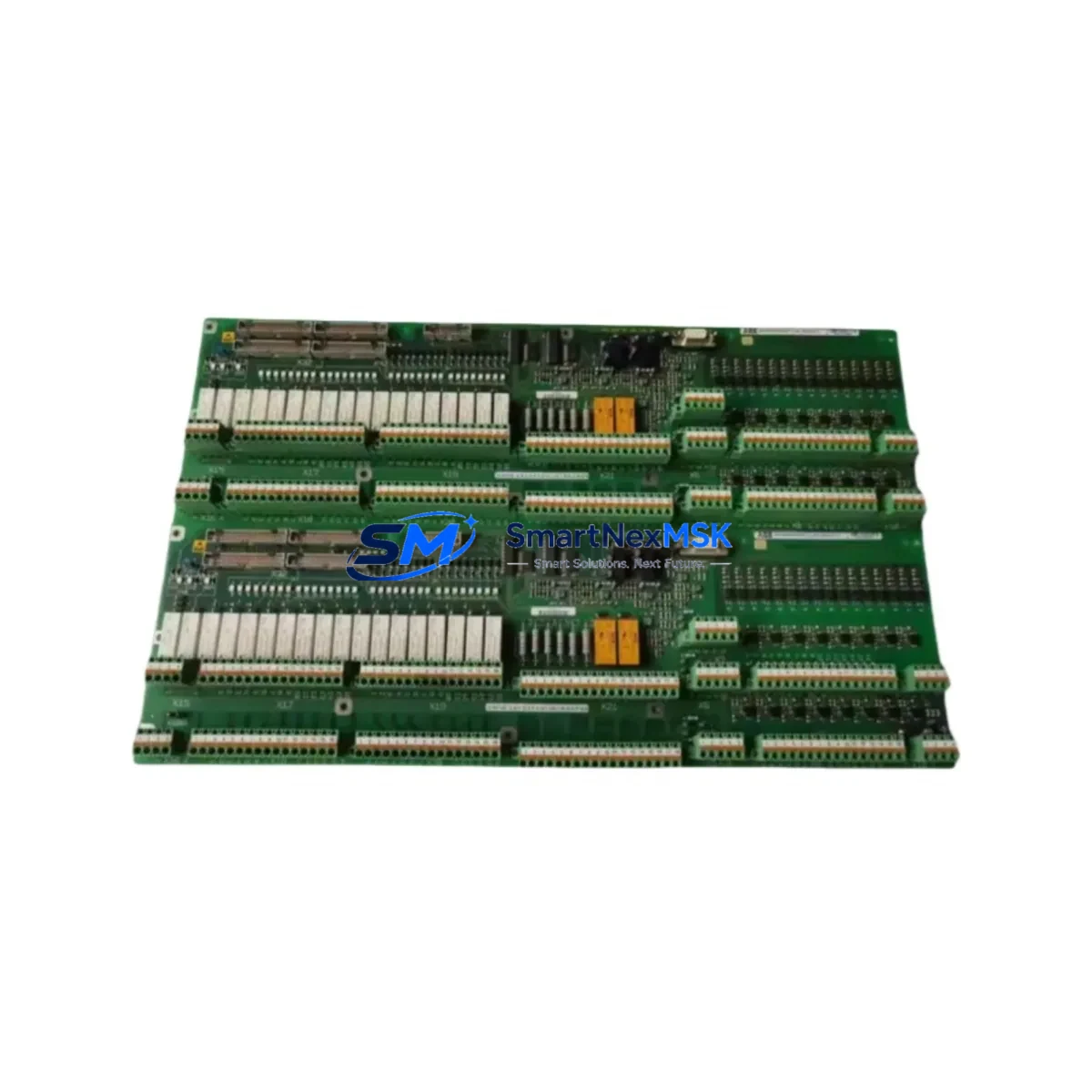
| Part Number | 3BHB007437P0002 |
| Module Type | M3V10-7/0-0 YYN0 — Inverter / VFD Drive Module |
| Compatible Platform | ABB ACS6000 Medium-Voltage Drive System |
| Series Compatibility | M3V Series (M3V10, M3V12 variants); ACS6000 R8i / R8i+ frames |
| Backplane Interface | Standard ACS6000 fiber-optic DDCS backplane; no adapter required |
| Communication Compatibility | DDCS (Distributed Drive Communication System); compatible with RDCO-02/03 adapters |
| Installation Requirement | Rack-mount into existing ACS6000 cabinet; verify DC bus voltage rating before swap |
| Replacement Recommendation | Direct replacement for failed or end-of-life M3V10-7/0-0 YYN0 units; no firmware re-flash required in most configurations |
| Commissioning Focus | Verify module address DIP switches, re-confirm DDCS node ID, check gate driver fiber connections, run self-test via DriveWindow or DriveDebug |
| Warranty | 12-Month Warranty — covers manufacturing defects and functional failure under normal operating conditions |
Retrofit Planning for Existing Automation Systems
Successful integration of the 3BHB007437P0002 into an existing ACS6000 installation requires a structured pre-replacement audit. Begin by documenting the existing cabinet layout, including the position of the AINT-02C interface board, the APBU-44C pulse encoder interface unit, and any installed RDCO-02 DDCS communication adapters. These components interact directly with the M3V drive module and must be confirmed operational before the new unit is energized.
Power supply integrity is a critical checkpoint. The ACS6000 system relies on a dedicated APOW-01 auxiliary power supply module to feed control electronics. Confirm that the auxiliary supply output voltages (typically +24 VDC and ±15 VDC rails) are within tolerance before inserting the replacement module. A degraded APOW-01 is a common root cause of repeated module failures and must be ruled out during the retrofit process.
Terminal wiring on the M3V module follows the standard ACS6000 fiber-optic topology. All gate drive signals are transmitted via plastic optical fiber (POF) links between the AGDR-81C gate driver board and the IGCT power semiconductors. Inspect all fiber connectors for contamination or mechanical damage before reconnecting. Bent or cracked POF links will cause asymmetric firing faults that are difficult to diagnose without an oscilloscope or DriveDebug trace.
For installations that include an IOEC-04 I/O extension module or an IOEC-03 analog I/O board, verify that the module address settings (configured via rotary switches on the IOEC units) have not been altered during the removal of the old drive module. Address conflicts on the DDCS ring will prevent the replacement module from communicating with the main control unit.
If the plant control system interfaces with the ACS6000 via a PROFIBUS DP adapter (RPBA-01) or a Modbus RTU adapter (RMBA-01), confirm that the fieldbus node address and baud rate parameters stored in the drive’s parameter group 51 (Ext Comm Module) are preserved. In most cases, these parameters survive a module swap if the RMIO-02 main control board remains in place, but a parameter backup via DriveWindow Light is strongly recommended before any hardware change.
HMI panels connected to the ACS6000 — including the CDP312R control panel or a remote operator panel via the panel bus — should be disconnected during the module swap to prevent spurious commands from being issued during power-up sequencing. Reconnect and verify all HMI display values (motor speed, output current, DC bus voltage) against known-good reference values after commissioning is complete.
Downtime Control During System Migration
Minimizing production downtime during an M3V module replacement requires advance preparation and a disciplined changeover sequence. Before scheduling the maintenance window, obtain a full parameter backup from the existing drive using DriveWindow or DriveDebug software. Export the parameter file and store it on an isolated engineering laptop — not on the plant network — to prevent accidental overwrite.
Where the process allows, arrange for a temporary bypass or manual control mode on the driven load (pump, compressor, or mill drive) so that production can continue at reduced capacity during the swap. Coordinate with the process control team to confirm that the PLC logic — typically running on an ABB AC500 series controller or a third-party DCS — has a defined fallback state for the drive-offline condition. This prevents nuisance trips or uncontrolled process upsets during the changeover window.
The physical module swap on an ACS6000 cabinet is typically achievable within 2–4 hours by a qualified drive service engineer, assuming all replacement parts are on-site and the cabinet is de-energized and locked out per LOTO procedures. Post-swap commissioning — including DDCS ring verification, gate driver self-test, and a no-load motor run — adds an additional 1–2 hours. Plan for a total maintenance window of 4–8 hours to allow for unexpected wiring or parameter issues without pressure to rush the energization sequence.
All units supplied by SMARTNEXMSK are pre-tested under load conditions prior to shipment and include a 12-month warranty against manufacturing defects. Shipment documentation includes a test report, packing list, and certificate of conformity to support incoming inspection at your facility.
Retrofit Support FAQ
Q1: Is the 3BHB007437P0002 a direct replacement for my existing M3V10-7/0-0 YYN0 module without firmware changes?
In the majority of ACS6000 installations, yes. The M3V10-7/0-0 YYN0 designation identifies a specific inverter module variant within the ACS6000 R8i frame family. Provided the RMIO-02 main control board and AINT-02C interface board remain in place, the replacement module will be recognized automatically on DDCS power-up. Firmware re-flashing is only required if the existing drive software version is below a known compatibility threshold — contact our technical team with your drive nameplate data for confirmation.
Q2: What wiring checks are mandatory before energizing the replacement module?
Prior to energization, verify all fiber-optic gate drive links between the AGDR-81C gate driver board and the IGCT stack, confirm DC bus capacitor pre-charge circuit continuity, check auxiliary power supply output voltages from the APOW-01, and inspect all DDCS fiber connections on the backplane. A megger test on the motor cable is also recommended if the cable has been disturbed during the cabinet work.
Q3: How do I confirm compatibility if my ACS6000 is an older revision with a different software version?
Provide us with the full drive nameplate data (type code, serial number, and software version from the CDP312R panel or DriveWindow) and we will cross-reference against our compatibility database. We stock multiple M3V module variants and can confirm the correct part number for your specific revision before shipment.
Q4: What does the 12-month warranty cover, and what is the claims process?
The 12-month warranty covers all manufacturing defects and functional failures under normal operating conditions as defined in the ABB ACS6000 technical manual. It does not cover damage resulting from incorrect installation, overvoltage events, or operation outside rated parameters. To initiate a warranty claim, contact sales@smartnexmsk.com with your order number, a description of the fault, and any available DriveDebug fault logs. Replacement or repair will be arranged within 5 business days of fault confirmation.
© 2026 SMARTNEXMSK. All rights reserved.
Original Source: https://smartnexmsk.com
Contact: sales@smartnexmsk.com | +86 18259474341


