ABB 3BHB013088R0001 Spare for GVC750 Series Automation: Spare Replacement & Industrial Downtime Risk Control
The ABB 3BHB013088R0001 (cross-reference: 5SHY3545L0010 / 3BHE009681R0101) is an original IGCT (Integrated Gate-Commutated Thyristor) Power Module designed for the ABB GVC750 GE101 series drive and converter systems. In high-availability industrial environments — including steel mills, paper machines, marine propulsion, wind energy converters, and large-scale motor drive applications — this module is a critical power switching component whose failure can result in immediate, unplanned production shutdowns. Maintaining a verified spare on-site is the single most effective strategy for minimizing mean time to repair (MTTR) and protecting operational continuity.
Spare Maintenance Table
| Parameter | Specification / Detail |
|---|---|
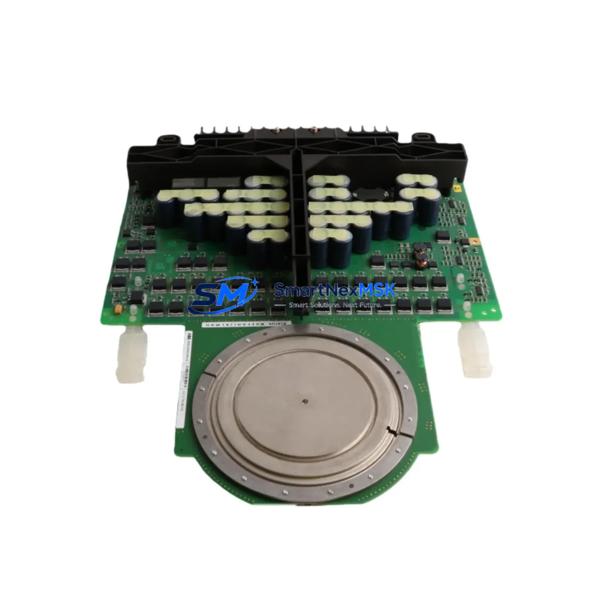
| Part Number | 3BHB013088R0001 |
| Cross Reference | 5SHY3545L0010 / 3BHE009681R0101 |
| Module Type | IGCT Power Module |
| Compatible Series | ABB GVC750 GE101 Drive / Converter System |
| Brand / Manufacturer | ABB (Original) |
| Country of Origin | Germany |
| Weight | 2,700 g (approx.) |
| Application Environment | Heavy industrial: steel, paper, marine, wind, large motor drives |
| Compatibility Verification | Confirmed against GVC750 GE101 series hardware revision |
| Installation | Direct drop-in replacement; follow ABB GVC750 commissioning procedure |
| Pre-Shipment Testing | Function-tested and inspected before dispatch |
| Warranty | 12 Months from date of shipment |
| Lead Time | In-stock; ships within 1–3 business days |
| Long-Term Supply | Available for repeat orders and blanket purchase agreements |
Maintenance Planning for Continuous Operation
When a maintenance or procurement engineer schedules replacement of the 3BHB013088R0001 IGCT module, a thorough inspection of the surrounding electrical circuit is essential to prevent repeat failures and ensure the drive system returns to full rated performance. The IGCT module does not operate in isolation — it is part of an integrated power conversion chain within the GVC750 cabinet.
During planned or corrective maintenance, engineers should simultaneously inspect the GVC750 gate unit board (3BHE009681R0101), which provides the gate drive signal directly to the IGCT. A degraded gate unit can cause premature IGCT failure even after a new module is installed. The ABB AGDR-81C / AGDR-71C gate driver cards, where applicable, should be checked for proper signal output and isolation integrity.
The DC link capacitor bank and associated DC bus fuses must be inspected for signs of thermal stress, bulging, or increased ESR — a failed IGCT often indicates an upstream overvoltage or current surge event that may have stressed these components. Likewise, the snubber capacitors and snubber resistors mounted adjacent to the IGCT should be measured and replaced if values are out of tolerance.
On the control side, the ABB RDCU-02C or RDCU-12C control unit (the main drive control board) should be verified for active fault logs and firmware integrity. Communication between the control unit and the power module is routed through the DDCS fiber optic link; inspect fiber connectors and transceivers for contamination or physical damage. If the system uses an ABB NPBA-12 or NIBA-01 fieldbus adapter for PROFIBUS or DeviceNet integration, confirm that communication is restored and stable after the IGCT swap.
The 24 VDC auxiliary power supply module feeding the gate driver and control boards should be load-tested — an intermittent auxiliary supply is a common root cause of nuisance IGCT trips. Terminal blocks and power wiring within the GVC750 cabinet should be re-torqued to specification, and any signs of arc tracking or insulation breakdown on the AC input contactor and pre-charge circuit should be addressed before re-energizing the drive.
For sites running legacy GVC750 systems beyond their original design life, this maintenance window is also an opportunity to assess the condition of the cooling fan assembly and heat sink thermal interface. IGCT modules are highly sensitive to junction temperature; degraded cooling directly shortens module service life. Documenting all replaced components in the site maintenance log supports future spare parts planning and warranty claims.
Site Replacement Workflow
Step 1 — Isolation & Lockout/Tagout: De-energize the GVC750 drive system following site LOTO procedures. Verify DC bus voltage has discharged to safe levels using a calibrated high-voltage meter before opening the cabinet.
Step 2 — Fault Documentation: Record all active and historical fault codes from the RDCU control unit. Photograph the existing IGCT module installation, noting cable routing, torque marks, and any visible damage.
Step 3 — Module Removal: Disconnect gate drive cables and power connections in the sequence specified in the ABB GVC750 hardware manual. Remove the 3BHB013088R0001 module using the correct extraction tool to avoid mechanical stress on the bus bars.
Step 4 — Compatibility Confirmation: Verify the replacement 3BHB013088R0001 part number, revision code, and 5SHY3545L0010 IGCT sub-assembly marking against the drive’s hardware revision label. Confirm the gate unit board revision is compatible.
Step 5 — Installation & Torque: Install the new module, torque all bus bar connections to ABB-specified values, and reconnect gate drive cables. Apply fresh thermal interface material to the heat sink contact surface if required.
Step 6 — Pre-Energization Checks: Verify insulation resistance of the DC bus, confirm auxiliary supply voltages, and clear all fault logs on the RDCU control unit before re-energizing.
Step 7 — Commissioning & Test Run: Perform a no-load test run, monitor drive output waveforms, and confirm all I/O signals, speed references, and fieldbus communications are functioning correctly before returning the drive to production service.
This structured workflow minimizes re-work risk, reduces total downtime, and ensures the replacement module operates within its rated parameters from first energization.
Spare Parts Support FAQ
Q1: Is the 3BHB013088R0001 a direct replacement for the 5SHY3545L0010?
Yes. The 5SHY3545L0010 is the ABB Semiconductors IGCT sub-assembly that forms the core of the 3BHB013088R0001 module assembly. Both part numbers refer to the same functional unit as supplied for the GVC750 GE101 drive system. Always confirm the hardware revision of your GVC750 cabinet before ordering to ensure full compatibility.
Q2: What does the 12-month warranty cover?
All units are function-tested and inspected prior to shipment. The 12-month warranty covers manufacturing defects and functional failures under normal operating conditions. It does not cover damage resulting from incorrect installation, overvoltage events, or operation outside rated parameters. Warranty claims are supported with full documentation and technical assistance.
Q3: How should this spare be stored if not immediately installed?
Store the 3BHB013088R0001 in its original anti-static packaging in a dry, temperature-controlled environment (recommended: 15–35°C, relative humidity below 75% non-condensing). Avoid exposure to vibration, magnetic fields, or corrosive atmospheres. Inspect the module annually if held in long-term storage and verify gate unit integrity before installation.
Q4: Can you supply multiple units for a blanket spare parts agreement?
Yes. We support repeat orders, blanket purchase agreements, and scheduled delivery programs for maintenance teams managing multiple GVC750 drive systems or large installed bases. Contact our technical sales team to discuss volume pricing, lead time commitments, and consignment stock arrangements tailored to your site’s maintenance strategy.
© 2026 SMARTNEXMSK. All rights reserved.
Original Source: https://smartnexmsk.com
Contact: sales@smartnexmsk.com | +86 18259474341


