ABB APBU-44CE 3ABD68243262-D ACS Drive Spare: Rapid Replacement for Industrial Downtime Control
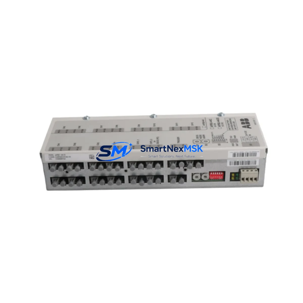
The ABB APBU-44CE (part number 3ABD68243262-D) is an original drive control board designed for ABB ACS series AC variable frequency drives. In industrial automation environments — from paper mills and water treatment plants to steel processing lines and HVAC systems — an unexpected drive control board failure can halt production within seconds. Stocking a verified spare of the APBU-44CE is one of the most cost-effective strategies a maintenance team can implement to protect uptime and reduce mean time to repair (MTTR).
This board serves as the central processing and gate-drive interface within the ACS drive cabinet. It manages PWM signal generation, fault diagnostics, I/O coordination, and fieldbus communication handshaking. When the APBU-44CE fails — typically presenting as drive fault codes, erratic output frequency, or complete loss of motor control — a like-for-like replacement with a tested original board is the fastest path to restoring operation without reconfiguring the entire drive system.
Spare Maintenance Table
| Parameter | Specification / Detail |
|---|---|
| Part Number | APBU-44CE / 3ABD68243262-D |
| Brand | ABB |
| Series Compatibility | ABB ACS Series AC Drives (ACS550, ACS580, ACS800, ACS880 — verify frame size) |
| Board Function | Drive Control PCB — PWM generation, fault logic, I/O interface, fieldbus coordination |
| Supply Voltage (Board) | 24 VDC internal logic supply (from drive SMPS) |
| Operating Temperature | 0°C to +55°C (ambient, with adequate cabinet ventilation) |
| Mounting | Direct board-level replacement; DIN-rail or chassis mount per drive frame |
| Connector Interface | Multi-pin ribbon and discrete terminal connectors (OEM-matched) |
| Origin | Germany (OEM manufactured) |
| Condition | Original, unused or refurbished-to-spec; tested prior to shipment |
| Warranty | 12 Months — covers manufacturing defects and functional failure under normal operating conditions |
| Lead Time | In-stock units ship within 1–3 business days; DHL / FedEx international available |
| Application Environment | Industrial automation, motor control centers, HVAC, pumping stations, conveyor systems |
| Maintenance Recommendation | Inspect every 12–24 months; replace immediately on fault code recurrence or thermal discoloration |
Maintenance Planning for Continuous Operation
When a maintenance or procurement engineer schedules replacement of the APBU-44CE, the board swap itself is rarely the only action required. A thorough site inspection of the surrounding drive cabinet is essential to prevent repeat failures and ensure the replacement board operates within its rated parameters.
Begin with the 24 VDC auxiliary power supply module (such as the ABB APOW-01 or equivalent SMPS board within the drive). A degraded internal power supply is one of the leading causes of premature control board failure — if the supply voltage is unstable or shows ripple beyond specification, the new APBU-44CE will be at risk from day one. Verify output voltage under load before installing the replacement board.
Next, inspect the I/O terminal block wiring and the AITC or AIMA analog input/output modules connected to the drive. Loose terminals, corroded contacts, or shielding failures on signal cables can inject noise into the control board’s analog input circuits, causing erratic speed references or false fault trips. Re-torque all terminal connections and verify cable shield grounding at a single point.
The fieldbus adapter module — whether a PROFIBUS RPBA-01, PROFINET FENA-21, or Modbus RMBA-01 — should also be inspected and re-seated. Communication faults between the PLC or DCS and the drive are frequently misdiagnosed as control board failures; confirming the adapter is functional before and after the board swap prevents unnecessary repeat work orders.
For drives integrated into a PLC-controlled system (Siemens S7-300/400/1500, Allen-Bradley ControlLogix, or Mitsubishi Q-series), verify that the drive’s parameter set is backed up before removal. The APBU-44CE stores drive-specific parameters; if the replacement board ships without the site-specific parameter file, the drive will revert to factory defaults and may not match the motor nameplate or process requirements. Use the ABB Drive Composer or Panel Bus tool to upload the parameter backup to the new board.
Inspect the gate driver board and IGBT power module connections while the drive is de-energized. A failing IGBT module can generate voltage spikes that damage the control board — replacing the APBU-44CE without checking the power stage is a common maintenance oversight. Look for signs of thermal stress, carbon tracking, or capacitor bulging on the DC bus capacitor bank.
The control panel (HMI keypad) — such as the ABB ACS-CP-C or ACS-CP-D — should be tested for communication continuity with the new board. Panel communication faults after a board swap are typically caused by a damaged panel cable or a mismatched firmware version. Confirm the panel firmware is compatible with the replacement board revision.
Finally, review the input fuses, main contactor, and EMC filter upstream of the drive. Overcurrent events that caused the original board failure may have also stressed these components. Replacing the APBU-44CE while leaving a marginal input fuse or a contactor with worn contacts in circuit increases the risk of a repeat failure event within the first operating cycle.
Site Replacement Workflow
Step 1 — Isolation and Lockout/Tagout: Isolate the drive from mains supply and apply LOTO. Wait a minimum of 5 minutes for DC bus capacitors to discharge below 50 VDC before opening the drive cabinet. Verify with a calibrated multimeter.
Step 2 — Parameter Backup: If the existing board is still partially functional, connect via the panel bus or USB adapter and export the full parameter set. Store the backup file with the equipment maintenance record.
Step 3 — Board Removal: Photograph all connector positions before disconnection. Label each ribbon cable and discrete connector with masking tape markers. Remove the APBU-44CE by releasing the board retaining clips and lifting straight out of the guide rails.
Step 4 — Visual Inspection of Cavity: Inspect the drive chassis for signs of moisture ingress, insulation debris, or rodent damage. Clean with dry compressed air if required.
Step 5 — Replacement Board Installation: Insert the new APBU-44CE along the guide rails until fully seated. Reconnect all connectors in the photographed sequence. Verify the fieldbus adapter module is firmly re-seated.
Step 6 — Parameter Restore and Commissioning: Power up the drive in local control mode. Upload the parameter backup. Verify motor nameplate data (voltage, current, frequency, speed) matches the parameter set. Run a no-load motor test before reconnecting the mechanical load.
Step 7 — Functional Test and Handover: Confirm remote control from PLC/DCS, verify all fault codes are cleared, and log the replacement in the site maintenance management system (CMMS). Update the spare parts inventory to trigger reorder of a replacement APBU-44CE for the next event.
Spare Parts Support FAQ
Q1: How do I confirm the APBU-44CE 3ABD68243262-D is compatible with my specific ACS drive frame size?
The APBU-44CE is used across multiple ACS series frame sizes, but compatibility depends on the drive’s hardware revision and firmware generation. Cross-reference the part number on the existing board’s label with the replacement unit before installation. If you provide your drive’s full type code (found on the drive nameplate), our technical team can confirm compatibility prior to shipment.
Q2: What does the 12-month warranty cover, and how is a warranty claim processed?
The 12-month warranty covers manufacturing defects and functional failure under normal operating conditions — defined as operation within the board’s rated voltage, temperature, and environmental specifications. Warranty claims are initiated by contacting sales@smartnexmsk.com with the order number, fault description, and site photos. Replacement or repair is dispatched within 5 business days of claim verification.
Q3: Is the board tested before shipment, and what documentation is provided?
Yes. Each APBU-44CE unit undergoes functional bench testing prior to dispatch, verifying power-up, communication interface, and I/O response. A test report is available on request. Units are shipped in anti-static packaging with foam protection to prevent transit damage.
Q4: What is the recommended spare parts stocking strategy for ACS drive control boards?
For critical production lines with a single drive controlling a key process, a minimum of one APBU-44CE spare per drive type is recommended. For facilities operating multiple ACS drives of the same frame size, a shared pool of 2–3 boards per 10 drives is a common industry practice. Long-lead-time sites (remote locations or facilities with limited logistics access) should consider holding a 24-month buffer stock given the potential for supply chain disruption on legacy drive components.
© 2026 SMARTNEXMSK. All rights reserved.
Original Source: https://smartnexmsk.com
Contact: sales@smartnexmsk.com | +86 18259474341


