ABB DI651 Maintenance-Ready Spare for S800 I/O Automation
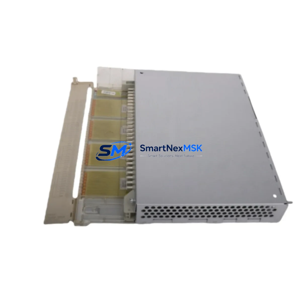
The ABB DI651 is a 16-channel AC 115V digital input module designed for the S800 I/O system — one of ABB’s most widely deployed distributed I/O platforms in process automation, power generation, and continuous manufacturing environments. For maintenance engineers managing aging DCS infrastructure or planning scheduled overhauls, having a verified, original DI651 spare on the shelf is a direct line of defense against unplanned downtime. This module interfaces directly with ABB’s AC800M and AC800F controller families, and its replacement requires no firmware reconfiguration when the same hardware revision is used — making it one of the most operationally straightforward spares in the S800 ecosystem.
Whether you are responding to a field fault, executing a planned turnaround, or building a minimum viable spare parts inventory for a remote site, the DI651 represents a critical node in your digital input signal chain. Procurement engineers sourcing this module should confirm hardware revision compatibility with the installed base and verify that the replacement unit has been functionally tested prior to dispatch. All units supplied by SMARTNEXMSK are original ABB components, individually tested before shipment, and covered by a 12-month warranty.
Spare Maintenance Table
| Parameter | Specification |
|---|---|
| Part Number / SKU | DI651 |
| Brand | ABB |
| Series | S800 I/O |
| Module Type | Digital Input Module |
| Number of Channels | 16 channels |
| Input Voltage | AC 115V |
| Compatible Controllers | AC800M, AC800F (ABB DCS platforms) |
| Mounting | S800 I/O ModuleBus carrier / TB820 / TB840 |
| Communication Interface | ModuleBus (optical or electrical) |
| Operating Temperature | 0°C to +55°C |
| Protection Class | IP20 |
| Origin | Germany |
| Weight | Approx. 1,220 g (packaged) |
| Condition | Original, New / Surplus |
| Pre-shipment Testing | Functionally tested before dispatch |
| Warranty | 12 Months |
| Compatibility Verification | Confirmed against S800 I/O system architecture |
| Maintenance Application | Planned overhaul, emergency replacement, spare stock |
Maintenance Planning for Continuous Operation
When a DI651 module is flagged for replacement — whether through a diagnostic alarm on the AC800M controller, a failed channel during routine I/O loop testing, or physical damage identified during a control cabinet inspection — the replacement workflow extends beyond the module itself. A thorough maintenance engineer will treat the DI651 swap as an opportunity to audit the surrounding signal chain and cabinet infrastructure.
Start with the TB820 or TB840 ModuleBus Termination Unit, which the DI651 mounts onto. Inspect the carrier for bent pins, oxidation, or mechanical stress. If the carrier has been in service for more than five years in a high-humidity or high-vibration environment, consider replacing it alongside the module. Next, check the CI854 or CI858 communication interface module that connects the S800 I/O cluster to the AC800M controller — a degraded communication link can cause intermittent input faults that are misdiagnosed as module failures.
On the field wiring side, inspect the terminal blocks and field wiring connectors feeding the 16 input channels. AC 115V field signals are susceptible to insulation degradation over time, and a wiring fault on one channel can mask a genuine module fault or vice versa. If the installation includes signal isolators or signal conditioners upstream of the DI651 inputs, verify their output levels are within the module’s rated input threshold before declaring the module faulty.
For sites running mixed I/O configurations, also inspect adjacent modules in the same I/O cluster: the DO651 digital output module, AI810 or AI820 analog input modules, and any AO810 analog output modules sharing the same ModuleBus segment. A failing power supply feeding the I/O cluster — such as the SD821 or SD822 24VDC power supply module — can cause cascading faults across multiple I/O modules simultaneously. Confirming supply voltage stability before replacing the DI651 is a mandatory diagnostic step.
Finally, if the site uses an OP516 or Panel 800 series HMI for local monitoring, verify that the input status display updates correctly after module replacement to confirm successful re-commissioning. Documenting the replacement in the site’s maintenance management system with the new module’s serial number and hardware revision ensures traceability for future audits and warranty claims.
Site Replacement Workflow
Step 1 — Isolate and de-energize: Follow site LOTO (Lockout/Tagout) procedures. De-energize the AC 115V field circuits connected to the DI651 input channels before any physical intervention. Confirm zero-energy state with an appropriate voltage tester on all 16 input terminals.
Step 2 — Record configuration: Before removal, capture the module’s hardware revision label and note the slot position on the ModuleBus carrier. In the AC800M engineering tool (Control Builder M), verify the I/O configuration for this slot — no software changes should be required if the replacement module shares the same hardware revision.
Step 3 — Remove and replace: Disconnect the field wiring connector from the DI651. Release the module locking mechanism and slide it out of the TB820/TB840 carrier. Insert the replacement DI651, ensuring it seats fully and the locking tab engages. Reconnect the field wiring connector.
Step 4 — Re-energize and verify: Restore power to the I/O cluster. Monitor the AC800M controller for module recognition — the DI651 should appear online within seconds. Perform a channel-by-channel input verification using known field signal states. Confirm all 16 channels report correctly in the DCS faceplate or HMI display.
Step 5 — Document and close: Record the replacement in the site CMMS with the new module’s serial number, hardware revision, installation date, and technician ID. Update the spare parts inventory to trigger reorder of a replacement DI651 for the spare stock. This closed-loop process ensures the site maintains its minimum spare parts buffer at all times.
This workflow applies equally to planned maintenance windows and emergency callouts. The DI651’s hot-swap capability within the S800 I/O architecture — when the system is configured for redundant I/O — can further reduce effective downtime to near zero in critical process applications.
Spare Parts Support FAQ
Q1: Is this DI651 compatible with all hardware revisions of the S800 I/O system?
The DI651 is designed for the ABB S800 I/O platform and is compatible with TB820 and TB840 ModuleBus carriers used across AC800M and AC800F controller systems. Hardware revision compatibility should be confirmed against your installed base. SMARTNEXMSK can provide hardware revision details upon request before order confirmation to ensure a direct fit replacement.
Q2: What pre-shipment testing is performed on each DI651 unit?
Every DI651 unit is functionally tested before dispatch to verify channel integrity, module communication, and physical condition. Units are inspected for connector condition, label integrity, and absence of physical damage. A test report is available upon request. All units are shipped in anti-static protective packaging to prevent transit damage.
Q3: What is the warranty coverage and what does it include?
All DI651 modules supplied by SMARTNEXMSK carry a 12-month warranty from the date of shipment. The warranty covers functional failure under normal operating conditions and includes replacement or full refund at the buyer’s option. Warranty claims are processed within 5 business days of fault confirmation. The warranty does not cover damage resulting from incorrect installation, overvoltage events, or physical mishandling on site.
Q4: Can SMARTNEXMSK support long-term or repeat supply of DI651 modules for multi-site maintenance programs?
Yes. SMARTNEXMSK maintains stock of DI651 and related S800 I/O components to support ongoing maintenance programs, annual turnaround schedules, and emergency callout requirements. Framework supply agreements with agreed lead times and pricing are available for procurement teams managing multi-site ABB DCS installations. Contact sales@smartnexmsk.com to discuss volume requirements and supply continuity arrangements.
© 2026 SMARTNEXMSK. All rights reserved.
Original Source: https://smartnexmsk.com
Contact: sales@smartnexmsk.com | +86 18259474341


