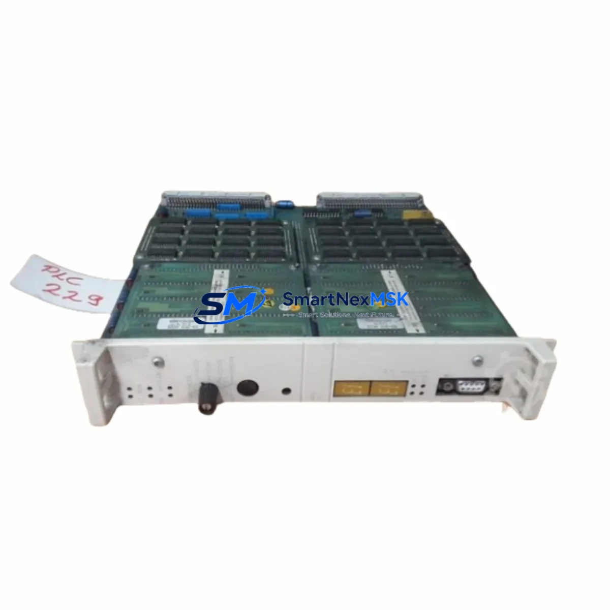
ABB DSPC171 57310001-CC/3 Retrofit-Ready CPU for DSPC Series Control Systems
The ABB DSPC171 57310001-CC/3 is a high-reliability central processing unit designed for seamless integration into legacy DSPC Series distributed control systems. As production lines built around the Advant Controller 400 platform age beyond their original service cycles, the DSPC171 57310001-CC/3 has become one of the most sought-after retrofit components for engineers tasked with modernizing control cabinets without triggering a full system overhaul. Whether you are replacing a failed unit, building a spare-parts buffer, or executing a phased upgrade across multiple production cells, this module delivers the processing continuity and protocol compatibility your existing infrastructure demands.
Sourced directly from verified industrial supply channels, each DSPC171 57310001-CC/3 unit shipped by SMARTNEXMSK undergoes pre-shipment functional verification to confirm firmware integrity, backplane interface continuity, and communication link stability before dispatch. All units carry a 12-month warranty covering manufacturing defects and functional failures under normal operating conditions.
Upgrade Compatibility Table
| Parameter | Details |
|---|---|
| Compatible Platform | ABB Advant Controller 400 (AC 400) Series |
| Replaces / Upgrades | DSPC171, DSPC172, DSPC110, DSPC111 CPU variants |
| Backplane Interface | S100 I/O Bus; compatible with DSBC172, DSBC176 bus carriers |
| Communication Protocol | Advant Fieldbus 100 (AF 100); MasterBus 300 compatible |
| Power Supply Requirement | 24 VDC via DSPM module; verify DSPM-A or DSPM-B variant before swap |
| Installation Format | Standard DSPC rack slot; no mechanical modification required |
| Firmware Compatibility | Compatible with existing AMPL / Control Builder M application programs |
| HMI Interface | Compatible with Advant Station 500 series operator panels |
| Replacement Recommendation | Direct drop-in for same-series CPU; verify rack address DIP switch settings |
| Commissioning Focus | Module address, I/O channel mapping, watchdog timer reset, comms link test |
| Warranty | 12 Months — covers manufacturing defects and functional failures |
Retrofit Planning for Existing Automation Systems
A successful DSPC171 57310001-CC/3 retrofit begins well before the module arrives on site. Engineers should start by auditing the existing rack configuration, typically a DSBC172 or DSBC176 bus carrier assembly, to confirm that the backplane connectors are free of corrosion and that the S100 I/O bus termination resistors are correctly seated. The DSPM power supply module feeding the CPU slot must be load-tested: the DSPC171 draws up to 3.5 W from the 24 VDC rail, and an aging DSPM-A unit operating near its rated output may exhibit voltage droop under combined CPU and I/O load, causing intermittent resets that are difficult to diagnose after the new module is installed.
Terminal wiring on the associated DSDO115 digital output modules and DSDI110 digital input modules should be photographed and documented before any rack work begins. In many legacy installations, field wiring labels have faded or been relabeled inconsistently over years of maintenance. Capturing the as-found state protects against wiring errors during reassembly and accelerates the post-swap I/O verification loop.
The DSPC171 57310001-CC/3 communicates over Advant Fieldbus 100, and the AF 100 segment connecting it to peer controllers or to the DSMB176 MasterBus 300 interface module must be checked for correct bus termination at both physical ends. A missing or double-terminated AF 100 segment is a common source of communication faults that appear only under load, after the replacement CPU has been running for several hours. Verify the DSMB176 node address and baud rate settings match the network configuration stored in the Control Builder M project before powering the new module.
For sites running Advant Station 500 series HMI panels, confirm that the operator station’s communication driver is configured to poll the correct CPU node address. If the failed DSPC171 was operating at a non-default node address, the replacement unit’s DIP switch bank must be set to match before rack insertion — attempting to change the node address after the module is live will interrupt all HMI data exchange and may trigger process alarms. Where the HMI project references tag names mapped to specific I/O channel addresses on DSAI130 analog input modules or DSAO120 analog output modules, a channel-by-channel signal verification pass is recommended as part of the commissioning sign-off procedure.
Sites that also operate DSCB110 communication bus modules or DSCS141 serial communication modules in the same control cabinet should note that these modules share the S100 bus bandwidth with the CPU. After the DSPC171 replacement, a bus load analysis using the diagnostic tools in Control Builder M will confirm that scan cycle times remain within the application’s configured limits. If scan time margins are tight, consider whether any DSAI or DSAO modules can be moved to a secondary rack to redistribute bus load before the retrofit window closes.
Downtime Control During System Migration
Minimizing unplanned downtime during a DSPC171 57310001-CC/3 swap requires a structured pre-outage preparation sequence. At least 48 hours before the scheduled maintenance window, upload and archive the current application program from the existing CPU using Control Builder M. Store the backup on an isolated engineering workstation and verify the file checksum. A second backup copy should be written to a removable medium and kept physically separate from the primary engineering station — this protects against workstation failure during the swap window itself.
Before removing the failed or end-of-life DSPC171, record all active process values, setpoints, and interlock states from the Advant Station 500 HMI. For continuous process applications, coordinate with operations to place the affected control loops in manual mode and confirm that downstream equipment — drives, valves, and safety interlocks — is in a safe hold state. The actual module swap on a properly prepared rack takes under five minutes: release the front panel locking screws, extract the module along the card guide rails, insert the replacement DSPC171 57310001-CC/3, and reseat the locking screws. The module will perform its internal self-test sequence on power-up, indicated by the RUN LED cycling through its initialization pattern.
After the module reaches RUN state, download the archived application program and perform a forced I/O scan to verify that all DSDI, DSDO, DSAI, and DSAO channel values match the pre-outage recorded states. Restore control loops to automatic mode in a staged sequence, starting with the least critical loops and progressing to primary process control. Document the total outage duration, the commissioning test results, and the firmware version of the replacement module in the site maintenance log. This record supports future warranty claims and provides the baseline for the next planned maintenance interval.
Retrofit Support FAQ
Q: Is the DSPC171 57310001-CC/3 a direct drop-in replacement for other DSPC-series CPU variants such as the DSPC172 or DSPC110?
A: The DSPC171 57310001-CC/3 is physically and electrically compatible with the same rack slot used by DSPC172 and DSPC110 modules on the S100 bus backplane. However, firmware feature sets differ between variants. Before substituting across part numbers, verify that the application program compiled under Control Builder M does not reference CPU-specific function blocks or memory map addresses that are exclusive to the original variant. In most standard ladder and function block programs, the DSPC171 is a functional replacement; confirm with a test download in a non-production environment where possible.
Q: What wiring changes are required when installing the DSPC171 57310001-CC/3 as a replacement?
A: No field wiring changes are required at the CPU slot level — the DSPC171 connects to the system exclusively through the backplane bus connector. Field wiring terminations on associated I/O modules (DSDI, DSDO, DSAI, DSAO) remain unchanged. The only physical adjustment required is the DIP switch setting for the module node address, which must match the address of the unit being replaced. Confirm the address setting against the Control Builder M hardware configuration before powering the rack.
Q: How is compatibility with the Advant Fieldbus 100 network verified after installation?
A: After the replacement DSPC171 reaches RUN state, use the diagnostic view in Control Builder M to check the AF 100 communication status for each configured node. All peer nodes — including any DSMB176 MasterBus 300 interface modules and remote I/O stations — should show active communication status within 30 seconds of the CPU completing its initialization sequence. If any node shows a communication fault, verify bus termination at both physical ends of the AF 100 segment and confirm that the baud rate setting on the replacement module matches the network configuration.
Q: What does the 12-month warranty cover, and what is the process for a warranty claim?
A: The 12-month warranty covers manufacturing defects and functional failures under normal operating conditions, including backplane interface faults, communication link failures, and CPU processing errors that are not attributable to incorrect installation, overvoltage, or physical damage. To initiate a warranty claim, contact SMARTNEXMSK at sales@smartnexmsk.com with the order reference number, a description of the observed fault, and the site commissioning record. Replacement units are dispatched after fault verification, and return shipping of the defective module is arranged by SMARTNEXMSK at no cost to the customer within the warranty period.
© 2026 SMARTNEXMSK. All rights reserved.
Original Source: https://smartnexmsk.com
Contact: sales@smartnexmsk.com | +86 18259474341


