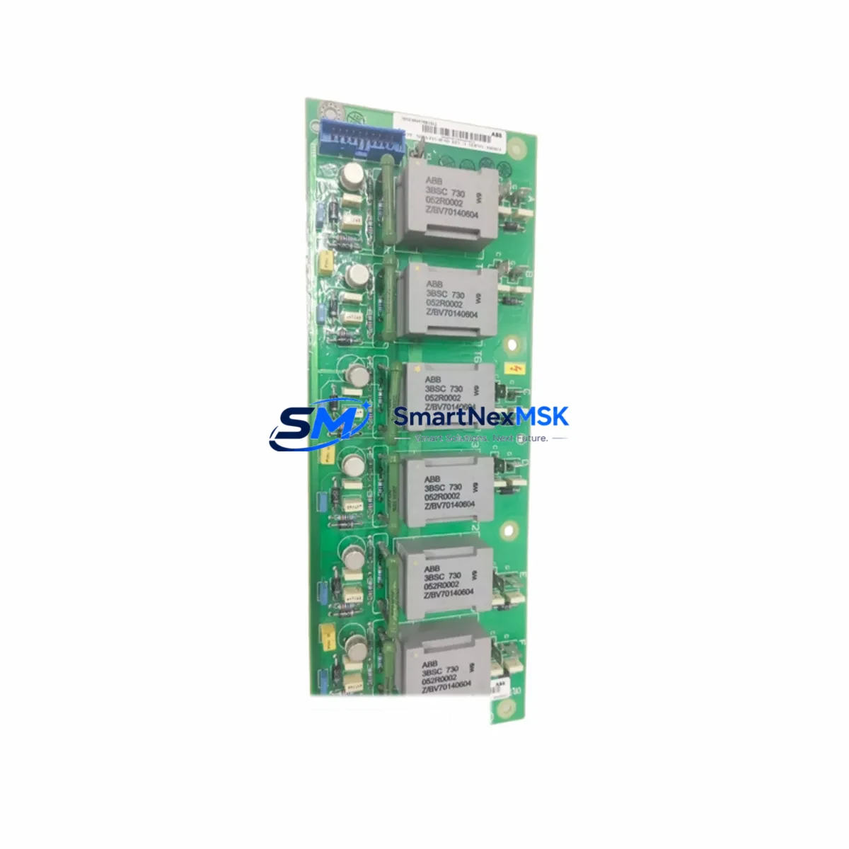
ABB LPFLD48 Retrofit-Ready Field Power Supply for LPFLD Series Control Systems
The ABB LPFLD48 is a 48 VDC DIN-rail-mounted field power supply engineered for seamless integration into legacy and modernized ABB control architectures. As a retrofit-ready replacement for discontinued LPFLD Series modules, the LPFLD48 addresses the growing demand for reliable spare parts, system upgrades, and control cabinet refurbishments across process automation, power distribution, and discrete manufacturing environments. Whether you are restoring an aging control panel or executing a planned migration to a newer ABB platform, the LPFLD48 delivers the electrical performance and form-factor compatibility required to minimize engineering rework and reduce overall project risk.
Upgrade Compatibility Table
| Parameter | Details |
|---|---|
| SKU / Part Number | LPFLD48 |
| Brand / Series | ABB / LPFLD Series |
| Output Voltage | 48 VDC |
| Mounting | DIN Rail (35 mm) |
| Replacement Target | Discontinued LPFLD Series field power supplies |
| Interface Compatibility | Standard terminal block wiring; compatible with ABB AC500, S800 I/O, and Symphony Plus field bus architectures |
| Communication Compatibility | Passive power module — no protocol dependency; compatible with PROFIBUS, PROFINET, Modbus, and FOUNDATION Fieldbus installations |
| Installation Requirement | Verify rail spacing, terminal pitch, and cabinet grounding before installation |
| Retrofit Recommendation | Direct drop-in for same-voltage LPFLD variants; verify load current rating against existing wiring harness |
| Commissioning Focus | Output voltage calibration, load regulation check, and downstream I/O module power-on sequencing |
| Warranty | 12 Months — covers manufacturing defects and functional failure under normal operating conditions |
Retrofit Planning for Existing Automation Systems
Successful integration of the LPFLD48 into an existing control system begins with a thorough audit of the current power distribution architecture. In most LPFLD Series installations, the field power supply feeds a shared 48 VDC bus that powers terminal modules, signal conditioners, and remote I/O clusters. Before removing the legacy unit, engineers should document the existing terminal wiring layout, confirm the load current drawn by all downstream consumers, and verify that the LPFLD48’s output rating meets or exceeds the aggregate demand.
In ABB AC500 PLC installations, the LPFLD48 typically operates alongside the PM5xx or PM5xx-ETH central processing units, supplying field-side power to CI5xx communication interface modules and DI/DO expansion modules mounted on the same TB5xx terminal base. When the control cabinet also houses ABB S800 I/O modules — such as the AI810, AO810, DI810, or DO810 — the field power rail must be carefully segmented to prevent cross-interference between analog and digital supply domains. The LPFLD48’s regulated output and low ripple characteristics make it well suited for mixed analog/digital I/O environments.
For installations that include ABB Symphony Plus DCS components, the LPFLD48 can serve as a replacement field power source for legacy Harmony or Network 90 power distribution panels. In these scenarios, the engineering team should cross-reference the original power module’s terminal assignment against the LPFLD48’s wiring diagram, paying particular attention to the positive and negative bus bar connections, chassis ground bonding, and any fused branch circuits feeding individual field devices. If the original installation used an ABB LPFLD24 or LPFLD110 variant, a voltage-level mismatch must be resolved before the LPFLD48 can be substituted.
Communication continuity is another critical consideration during retrofit. In systems where the field power supply also energizes PROFIBUS DP repeaters, Modbus RTU converters, or FOUNDATION Fieldbus H1 segment couplers, a power interruption during module swap will cause a temporary loss of process data. To mitigate this, plan the replacement during a scheduled maintenance window, use a portable UPS to maintain bus voltage during the changeover, and verify that the PLC’s watchdog timer and fail-safe output configuration are set appropriately to hold the last known state during the brief outage.
Where the retrofit involves upgrading from an older ABB Advant OCS or MOD 300 platform to a current AC500 or Symphony Plus architecture, the LPFLD48 may be installed as part of a broader I/O migration that includes replacing legacy S100 or S200 I/O modules with modern S800 equivalents, re-terminating field cables on new TB5xx terminal bases, and updating the control program in ABB Control Builder or 800xA Engineering Studio. In these projects, the power supply replacement is typically the first physical step, followed by rack and backplane installation, I/O module seating, and finally program download and HMI screen validation.
Downtime Control During System Migration
Minimizing unplanned downtime is the primary operational constraint in any field power supply replacement project. The recommended approach for LPFLD48 installation in a live production environment follows a structured sequence: first, perform a full backup of the PLC program, HMI project files, and communication configuration using ABB Control Builder or the 800xA backup utility; second, photograph or scan the existing terminal wiring before disconnection; third, isolate the field power circuit using the upstream MCB or fused disconnect, confirm de-energization with a calibrated multimeter, and then proceed with module removal and LPFLD48 installation.
To protect original program logic during the migration, ensure that the CPU retentive memory area — which stores counter values, timer presets, and data block contents — is preserved in battery-backed RAM or uploaded to the engineering station before power is removed. In AC500 systems, the PM5xx CPU supports a SD card backup function that captures the complete project snapshot, including hardware configuration, I/O mapping, and communication parameters. This snapshot can be used to restore the system to its pre-migration state if commissioning issues arise.
After the LPFLD48 is installed and the field power circuit is re-energized, perform a systematic power-on check: verify output voltage at the bus bar terminals, confirm that all downstream I/O modules report healthy status in the diagnostic display, and check that communication links to PROFIBUS slaves, Modbus devices, or Fieldbus segments are re-established within the expected timeout window. HMI screens should be validated against the live process values to confirm that tag mapping and scaling remain intact. A final load regulation test — applying rated load and measuring output voltage stability — completes the commissioning record and supports the 12-month warranty documentation.
Retrofit Support FAQ
Q1: Is the LPFLD48 a direct drop-in replacement for all LPFLD Series power supplies?
The LPFLD48 is a direct replacement for LPFLD Series units with a 48 VDC output rating. If your existing installation uses an LPFLD24 (24 VDC) or LPFLD110 (110 VDC) variant, the LPFLD48 is not a voltage-compatible substitute. Please confirm the output voltage of your legacy module before ordering. For mixed-voltage cabinets, our technical team can advise on the correct replacement SKU.
Q2: What wiring changes are required during installation?
In most cases, the LPFLD48 uses the same terminal pitch and DIN rail footprint as the original LPFLD Series module, allowing direct re-termination of existing field cables without re-routing. However, engineers should verify the terminal block torque specification, confirm that wire ferrules are in good condition, and check that the cable cross-section is rated for the LPFLD48’s maximum output current. Any changes to the grounding arrangement should be documented in the as-built drawings.
Q3: How is compatibility with the existing PLC program verified before go-live?
The LPFLD48 is a passive power module and does not interact with the PLC program directly. Compatibility verification focuses on the electrical interface: confirm that the output voltage and current capacity match the requirements of all powered field devices, and that the power-on sequencing does not cause false inputs or unexpected output states during startup. A staged power-on test — energizing the field power supply before enabling the PLC outputs — is recommended to catch any wiring errors before full production restart.
Q4: What does the 12-month warranty cover, and how is a claim initiated?
The 12-month warranty covers manufacturing defects and functional failures under normal operating conditions, including output voltage out-of-specification, thermal shutdown under rated load, and terminal block failure. Warranty claims are initiated by contacting our sales team with the original order reference, a description of the fault symptom, and photographic evidence of the installation. Units confirmed defective under warranty are replaced or refunded at no additional cost. Warranty does not cover damage resulting from incorrect installation voltage, reverse polarity connection, or physical impact.
© 2026 SMARTNEXMSK. All rights reserved.
Original Source: https://smartnexmsk.com
Contact: sales@smartnexmsk.com | +86 18259474341


