ABB RDCU-12C ASXR7360 Retrofit-Ready Drive Control Unit for ACS800 Control Systems
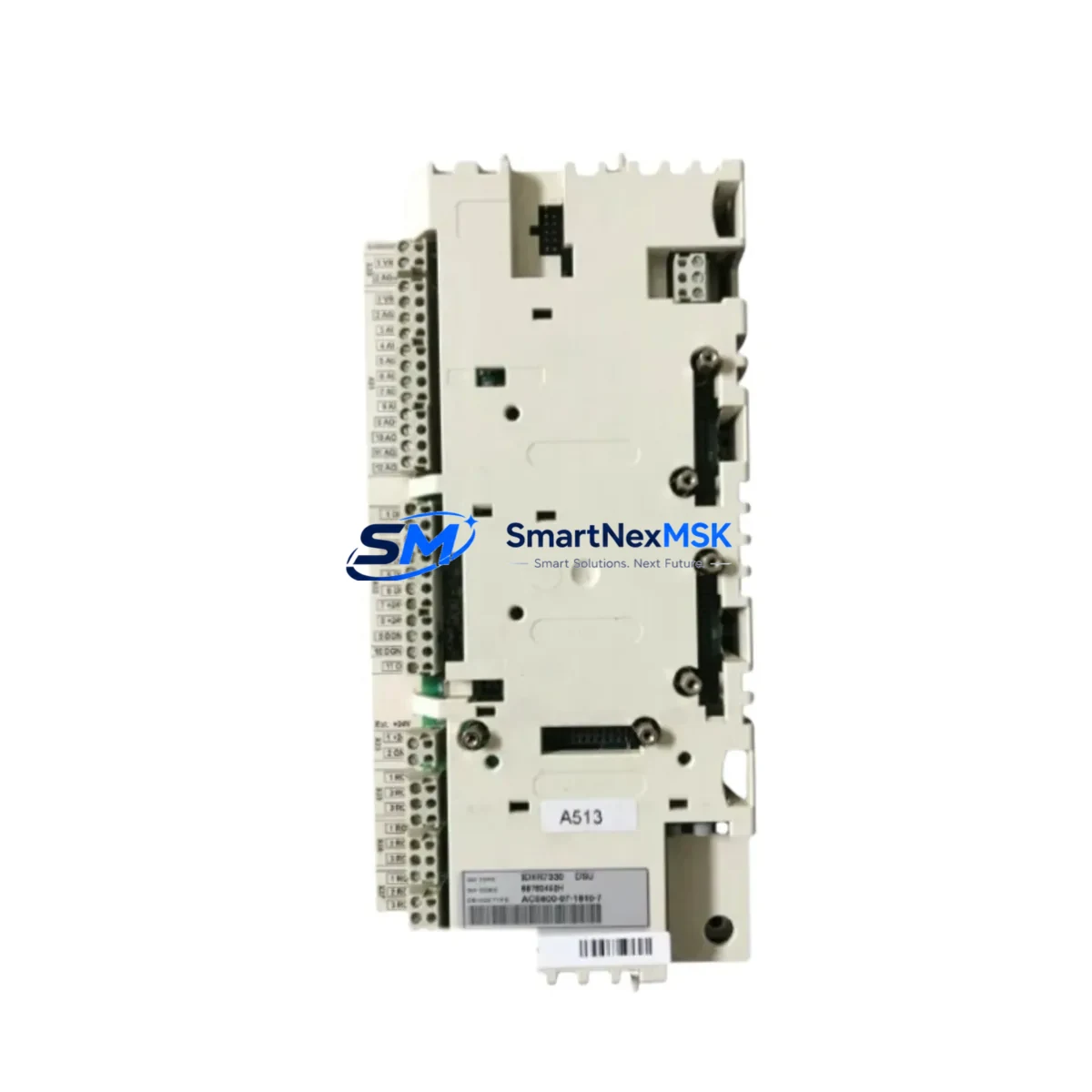
The ABB RDCU-12C (catalog reference ASXR7360) is a retrofit-ready drive control unit engineered for seamless integration into existing ACS800 and ACS600 frequency converter platforms. As legacy drive systems approach end-of-life or face discontinued spare parts availability, the RDCU-12C provides a verified drop-in replacement path that preserves original wiring topology, DDCS fiber-optic communication links, and application program logic — minimizing engineering rework and unplanned downtime during system modernization.
This control unit is widely deployed in retrofit projects across paper mills, cement plants, marine propulsion systems, metal processing lines, and municipal water treatment facilities where ACS800 multi-drive cabinets remain in active service. Its compatibility with the ACS800 RDCU slot architecture means that field engineers can execute a like-for-like swap without modifying the main circuit board, power supply wiring, or I/O terminal assignments.
Upgrade Compatibility Table
| Parameter | Detail |
|---|---|
| Replaces / Compatible With | ABB ACS800, ACS600 series drive control boards |
| Catalog / Part Number | RDCU-12C / ASXR7360 |
| Communication Protocol | DDCS (Distributed Drive Control System) fiber-optic |
| Mounting / Installation | Direct slot replacement in ACS800 control section; no mechanical modification required |
| Terminal Wiring Compatibility | Compatible with original X1–X4 terminal blocks; verify 24 VDC auxiliary supply capacity |
| Backplane Interface | Standard ACS800 RDCU backplane connector; confirm firmware revision alignment |
| Program / Parameter Compatibility | Supports upload/download via DriveWindow or DriveStudio; parameter set backup recommended before swap |
| HMI Panel Compatibility | Compatible with CDP312R and ACS-CP-C control panels |
| Replacement Recommendation | Direct replacement; no hardware adaptation required for standard ACS800 frames R2–R8 |
| Commissioning Focus | Firmware version check, DDCS node address verification, I/O signal mapping confirmation |
| Warranty | 12 months from date of shipment; covers manufacturing defects and functional failure |
Retrofit Planning for Existing Automation Systems
A successful RDCU-12C retrofit begins well before the physical swap. Engineers should first audit the existing ACS800 drive cabinet to document the current firmware version stored on the RDCU board, the DDCS node address assigned in the multi-drive chain, and the parameter set governing motor control, speed references, and fault response logic. A full parameter backup using DriveWindow Light or DriveStudio should be completed and archived before any hardware is removed.
Power supply capacity is a critical checkpoint. The RDCU-12C draws its 24 VDC logic supply from the drive’s internal APBU-44C or APBU-12C pulse encoder interface unit or from an external 24 VDC rail. Verify that the existing SDCS-CON-4 or AINT-02C interface boards — if present in a mixed ACS600/ACS800 environment — are not sharing a supply rail that may be undersized for the replacement unit’s inrush profile.
Terminal wiring on the X1 digital input block and X2 analog reference block should be photographed and mapped before disconnection. In many legacy installations, the RMIO-11C or RMIO-12C I/O extension modules are daisy-chained to the RDCU via the DDCS fiber ring. These modules — along with any RDIO-01 relay output boards or RAIO-01 analog I/O expanders — must remain addressed correctly in the DDCS ring after the control unit is replaced. Confirm that the DDCS ring topology is intact and that the APOW-01 auxiliary power supply module is delivering stable voltage before powering up the new RDCU-12C.
For installations where the ACS800 communicates upstream to a DCS or SCADA via a PROFIBUS-DP fieldbus adapter (RPBA-01) or a Modbus RTU link through an RMBA-01 adapter, the fieldbus node address and baud rate settings stored in the RDCU parameter group 51 must be re-entered or restored from backup. Failure to restore these settings will result in a communication fault on first power-up, which is a common cause of unnecessary extended downtime during retrofit commissioning.
HMI screens connected via the CDP312R panel or a third-party SCADA system referencing ACS800 parameter addresses will continue to function without modification, provided the parameter structure of the replacement RDCU-12C firmware matches the original. If the firmware version has been updated, review the parameter delta list in the ACS800 firmware release notes to identify any renamed or renumbered parameters that may affect HMI display logic or alarm mapping.
Downtime Control During System Migration
Minimizing production downtime during an RDCU-12C swap requires a structured pre-outage preparation protocol. The recommended approach is to complete all documentation, parameter backup, and spare parts staging — including the replacement RDCU-12C, any required DDCS fiber patch cables, and a spare APOW-01 power module — during a scheduled maintenance window rather than during an emergency breakdown response.
The physical swap of the RDCU-12C can typically be completed within 30 to 60 minutes by a qualified drive engineer familiar with the ACS800 platform. The critical path items are: safe isolation of the drive cabinet (following LOTO procedures), removal of the fiber-optic DDCS connectors from the existing board, extraction of the control unit from the backplane slot, insertion of the replacement RDCU-12C, reconnection of fiber links, and restoration of the parameter set from backup.
Before returning the drive to automatic control, perform a manual jog test at reduced speed reference to confirm that the motor responds correctly to speed commands, that all digital inputs (run, stop, fault reset, speed reference select) are functioning, and that the DDCS communication link to any upstream APBU or AINT interface is confirmed fault-free. Log the commissioning test results and update the site maintenance record with the new board serial number and firmware version. This documentation supports the 12-month warranty claim process if a fault occurs within the warranty period.
Retrofit Support FAQ
Q1: Is the RDCU-12C a direct drop-in replacement for all ACS800 frame sizes?
The RDCU-12C is compatible with ACS800 single drive and multi-drive frames R2 through R8 that use the standard RDCU control unit slot. For ACS800-04 and ACS800-07 multi-drive configurations, verify the DDCS ring node count and confirm that the replacement unit’s firmware supports the number of inverter modules in the chain. Frame R1 configurations may use a different control board form factor — confirm the part number before ordering.
Q2: Can I reuse my existing parameter set after installing the RDCU-12C?
Yes, provided you have a complete parameter backup from the original board. Use DriveWindow Light or DriveStudio to restore the parameter set after installation. If the firmware version on the replacement RDCU-12C differs from the original, review the firmware release notes for any parameter changes before restoring. Parameters in groups 10 (Start/Stop/Dir), 20 (Limits), 30 (Fault Functions), and 51 (Fieldbus Adapter) are the most critical to verify.
Q3: What wiring changes are required when installing the RDCU-12C?
In a standard like-for-like replacement, no wiring changes are required. The X1 digital input terminal block, X2 analog reference block, and DDCS fiber connectors use the same pinout and connector types as the original RDCU board. However, if the original installation used non-standard wiring modifications or jumper configurations, document these before removal and replicate them on the replacement unit.
Q4: What does the 12-month warranty cover, and how is a claim initiated?
The 12-month warranty covers manufacturing defects and functional failure under normal operating conditions from the date of shipment. It does not cover damage caused by incorrect installation, overvoltage events, or operation outside the specified environmental ratings. To initiate a warranty claim, contact sales@smartnexmsk.com with the order reference, board serial number, fault description, and commissioning test records. Replacement units are dispatched after fault verification, and defective units must be returned for inspection.
© 2026 SMARTNEXMSK. All rights reserved.
Original Source: https://smartnexmsk.com
Contact: sales@smartnexmsk.com | +86 18259474341


