ABB RXMVB4 Retrofit-Ready Bistable Relay for RXMV Series Control Systems
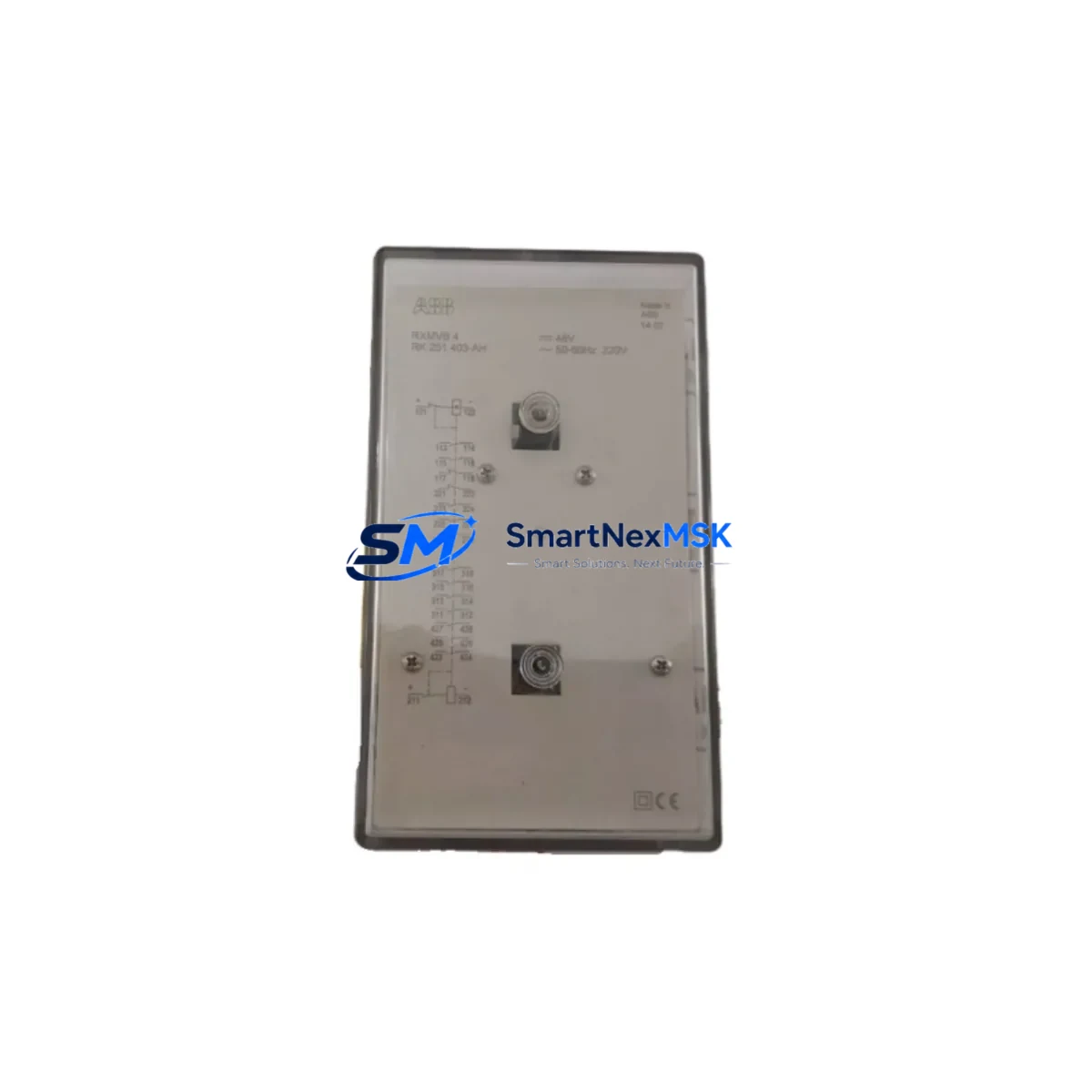
The ABB RXMVB4 is a bistable (latching) plug-in relay engineered for seamless integration into legacy RXMV Series relay panels and modern retrofit control cabinets alike. As industrial facilities transition away from discontinued relay platforms, the RXMVB4 stands out as a proven drop-in replacement that preserves existing wiring layouts, terminal assignments, and control logic without requiring panel redesign. Whether you are upgrading a protection relay panel, replacing a failed bistable element in a substation automation system, or migrating from an older ABB RXMV variant, the RXMVB4 delivers the electrical and mechanical compatibility your project demands.
Sourced directly from authorized supply channels and subject to full pre-shipment functional testing, each RXMVB4 unit is verified for coil continuity, contact resistance, bistable latch operation, and reset response before dispatch. A 12-month warranty covers all units against manufacturing defects, giving procurement engineers and maintenance teams the confidence to plan long-cycle replacements without risk.
Upgrade Compatibility Table
| Parameter | Detail |
|---|---|
| Compatible Series | ABB RXMV Series (RXMVB2, RXMVB4, RXMVB6 variants) |
| Relay Type | Bistable / Latching, Plug-in |
| Contact Configuration | 4-contact output (confirm coil voltage variant before ordering) |
| Mounting Interface | Standard RXMV plug-in socket – no socket replacement required |
| Coil Voltage Options | Verify against existing panel nameplate (24 VDC / 48 VDC / 110 VDC typical) |
| Communication Compatibility | Passive relay element; compatible with all upstream protection relay outputs (ABB REF, RET, RED series) |
| Replacement Recommendation | Direct drop-in for failed or end-of-life RXMVB4 units; verify coil polarity on bistable reset circuit |
| Commissioning Notes | Confirm latch/reset coil wiring; test bistable state retention after power interruption |
| Warranty | 12 Months – covers manufacturing defects, contact failure, and coil open-circuit |
| Origin | Germany (DE) – ABB manufactured |
Retrofit Planning for Existing Automation Systems
Replacing the RXMVB4 within a live protection or control panel requires a structured approach that accounts for the broader system architecture. In substation automation and industrial protection schemes, the RXMVB4 typically interfaces with ABB REF615 or REF630 feeder protection relays, receiving trip or close commands and latching the output state until a deliberate reset signal is applied. Before removing the existing unit, engineers should document the current wiring against the panel schematic, noting the latch coil terminal (typically L1/L2) and the reset coil terminal (R1/R2), as polarity reversal on a bistable coil is a common commissioning error that prevents proper state retention.
In retrofit projects involving older ABB RXMV Series panels, it is common to encounter companion components such as the RXMVB2 (2-contact variant) used for auxiliary signaling, the RXMVB6 (6-contact variant) for more complex interlocking schemes, and RXMA1 or RXMH2 auxiliary relays providing additional output expansion. The relay socket — typically an ABB RXZE2M4 or equivalent — should be inspected for contact wear and replaced if oxidation or pitting is observed, as a degraded socket will compromise the RXMVB4’s contact resistance performance regardless of the relay’s own condition.
For control cabinets integrating the RXMVB4 alongside programmable logic controllers, the relay’s bistable characteristic must be reflected in the PLC program logic. If the upstream controller is an ABB AC500 series PLC or a Siemens S7-300/S7-400 system, the program must account for the fact that the relay retains its last state through a power cycle — a behavior that differs from standard monostable relays and can cause unexpected output states on system restart if not handled in the startup routine. Migrating from a monostable relay scheme to a bistable layout therefore requires a review of the PLC’s power-up initialization sequence and any associated HMI screen logic that displays relay status.
Where the retrofit involves communication protocol migration — for example, transitioning from hardwired relay logic to IEC 61850 GOOSE messaging via an ABB COM600 or COM610 gateway — the RXMVB4 continues to serve as the physical output element, receiving commands from the gateway’s binary output module. In such architectures, the relay’s wiring to the gateway’s DO (digital output) terminals must be verified against the gateway’s I/O configuration, and the GOOSE dataset mapping should be confirmed before energizing the circuit. Companion components in this communication chain often include the ABB REB500 busbar protection system, RTU560 remote terminal units, and fiber-optic patch panels for station bus connectivity.
Power supply capacity is another critical checkpoint. The RXMVB4’s coil draws a brief pulse current during latch and reset operations. In panels where multiple bistable relays share a common DC auxiliary supply — often a 110 VDC station battery backed by an ABB UNS0880 or similar battery charger — the aggregate inrush during simultaneous switching must be within the supply’s current rating. A load calculation should be performed before adding RXMVB4 units to an existing panel, particularly in retrofit scenarios where the original design did not anticipate the current relay count.
Downtime Control During System Migration
Minimizing control system downtime during an RXMVB4 replacement begins with pre-staging. Before the maintenance window opens, the replacement relay should be bench-tested: apply the rated latch coil voltage, confirm contact closure across all four outputs, apply the reset coil voltage, and confirm contact return to the open state. This functional verification — taking less than five minutes per unit — eliminates the risk of installing a defective component during a live outage window.
During the replacement itself, the bistable relay’s latched state should be recorded before removal. If the relay is in the latched (energized output) position, the downstream circuit — whether a circuit breaker close coil, a motor contactor, or an annunciator panel — must be placed in a safe state before the relay is unplugged. Failure to do so can result in an uncontrolled state change when the new relay is inserted in its default (unlatched) position. A temporary hardwired bypass or a manual override on the downstream device is the standard practice for maintaining control continuity during the swap.
After insertion of the new RXMVB4, the latch coil should be pulsed from the control system or a test set to restore the required output state before the bypass is removed. The reset function should then be tested under controlled conditions to confirm that the relay responds correctly to the reset signal and that the PLC or protection relay registers the state change on its binary input. Where an HMI is present — such as an ABB Ability System 800xA or a Wonderware InTouch station — the relay status display should be verified to confirm that the new unit’s contact state is correctly reflected in the SCADA or DCS visualization before the panel is returned to service.
For large-scale retrofit programs involving multiple RXMVB4 replacements across a substation or plant, a phased replacement schedule — replacing one relay per maintenance window — is strongly recommended over batch replacement. This approach limits the blast radius of any commissioning error and allows the maintenance team to build familiarity with the replacement procedure before tackling higher-criticality circuits.
Retrofit Support FAQ
Q1: Is the RXMVB4 a direct replacement for all RXMV Series bistable relays?
The RXMVB4 is a direct replacement for other RXMVB4 units within the RXMV Series. It is not pin-compatible with the RXMVB2 (2-contact) or RXMVB6 (6-contact) variants, as these use different socket configurations. Always confirm the contact count and coil voltage of the unit being replaced before ordering. If you are replacing an RXMVB2 or RXMVB6, contact our sales team for the correct variant.
Q2: How do I verify the coil voltage before ordering?
The coil voltage is printed on the relay body nameplate and is also specified in the panel wiring diagram under the relay’s terminal designation. Common voltages for RXMV Series relays are 24 VDC, 48 VDC, and 110 VDC. If the nameplate is illegible, the coil resistance can be measured with a multimeter and cross-referenced against the ABB RXMV Series datasheet to identify the voltage rating. We supply RXMVB4 units in all standard coil voltage variants — specify your requirement at the time of order.
Q3: What commissioning checks are required after installing the RXMVB4?
After installation, perform the following checks: (1) Apply the latch coil pulse and verify all four output contacts close using a continuity tester or the control system’s binary input feedback. (2) Apply the reset coil pulse and verify all contacts return to open. (3) Interrupt auxiliary power and restore it — confirm the relay retains its last latched or reset state (bistable behavior). (4) Verify that the upstream protection relay or PLC registers the correct contact state on its binary input channel. (5) Confirm HMI status displays match the physical relay state before returning the panel to service.
Q4: What does the 12-month warranty cover, and how is it claimed?
The 12-month warranty covers manufacturing defects including coil open-circuit, contact failure to make or break, and bistable latch mechanism failure under normal operating conditions. It does not cover damage resulting from incorrect coil voltage application, reverse polarity connection, or physical mishandling. To claim warranty, contact our sales team with the order reference number and a description of the fault. We will arrange a replacement unit dispatch or, where applicable, a technical review of the returned unit. Pre-shipment test records are retained for all dispatched units and can be provided upon request.
© 2026 SMARTNEXMSK. All rights reserved.
Original Source: https://smartnexmsk.com
Contact: sales@smartnexmsk.com | +86 18259474341


