ABB SDCS-PIN-4 3ADT314100R1001: Retrofit-Ready Power Interface Board for DCS800 Control Systems
The ABB SDCS-PIN-4 (part number 3ADT314100R1001) is a Power Interface Board designed for the ABB DCS800 series DC drive platform. As legacy DCS500 and DCS400 installations reach end-of-service life, the SDCS-PIN-4 serves as a critical retrofit component enabling engineers to modernize existing DC motor control systems without full drive replacement. Whether you are managing a planned upgrade or responding to an unplanned failure, this board provides a verified drop-in replacement path with full compatibility across the DCS800 drive family.
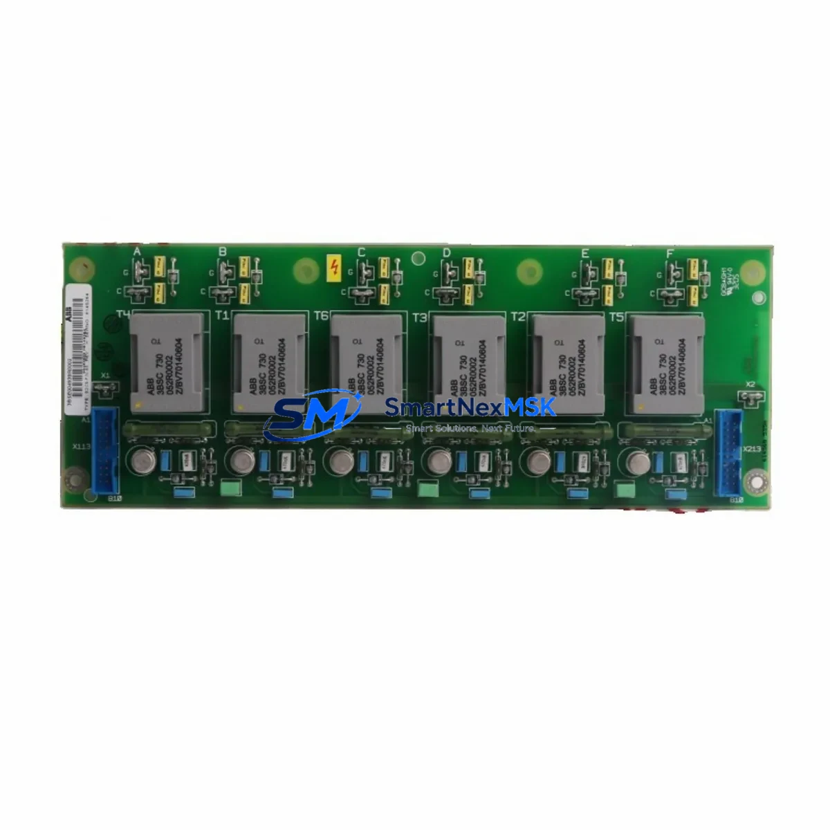
The SDCS-PIN-4 interfaces directly with the DCS800 control board stack, managing power feedback, gate pulse distribution, and thyristor firing signals. Its role in the drive’s power conversion chain makes it one of the most failure-sensitive components in high-cycle DC drive applications such as paper mills, steel rolling lines, crane hoists, and extruder drives. Sourcing a verified replacement with documented compatibility is essential to minimizing unplanned downtime and protecting existing motor and transformer assets.
Upgrade Compatibility Table
| Parameter | Details |
|---|---|
| Part Number | SDCS-PIN-4 / 3ADT314100R1001 |
| Compatible Drive Series | ABB DCS800 (all frame sizes) |
| Replaces / Upgrades From | SDCS-PIN-3, SDCS-PIN-2 (with firmware verification) |
| Backplane Interface | DCS800 internal bus connector — direct plug-in, no adapter required |
| Communication Compatibility | Compatible with SDCS-COM-8, SDCS-COM-81 fieldbus adapter boards (PROFIBUS, DeviceNet, Modbus) |
| Power Supply Requirement | 24 VDC auxiliary supply via SDCS-POW-4 or equivalent power supply board |
| Installation Requirement | Drive must be de-energized; follow DCS800 Hardware Manual section 5 for board swap procedure |
| Firmware Compatibility | Verify DCS800 firmware version ≥ 5.x via DriveWindow or DriveStudio before installation |
| Commissioning Tool | ABB DriveWindow 2 / DriveStudio via SDCS-COM-8 or USB-to-RS232 cable |
| Retrofit Recommendation | Replace SDCS-PIN-4 together with SDCS-DSL-4 gate driver board for full power stage restoration |
| Warranty | 12 Months — covers manufacturing defects and functional failure under normal operating conditions |
Retrofit Planning for Existing Automation Systems
A successful SDCS-PIN-4 retrofit begins well before the board arrives on site. Engineers should first audit the existing DCS800 drive cabinet to confirm the current firmware version stored on the SDCS-CON-F control board. If the drive has been running legacy firmware below version 5.0, a firmware update via DriveStudio is recommended prior to the board swap to ensure full parameter compatibility.
Next, verify the auxiliary power supply. The SDCS-POW-4 power supply board provides the 24 VDC rail that feeds the SDCS-PIN-4 and associated signal boards. A degraded SDCS-POW-4 is a common co-failure in aging DCS800 cabinets and should be inspected or replaced simultaneously to avoid repeat failures after the retrofit. Similarly, the SDCS-DSL-4 gate driver board, which works in tandem with the SDCS-PIN-4 to deliver firing pulses to the thyristor bridge, should be tested under load before sign-off.
Terminal wiring on the SDCS-PIN-4 follows the standard DCS800 backplane connector layout. No re-wiring of the main power terminals is required for a like-for-like replacement. However, if the retrofit is part of a broader I/O expansion — for example, adding encoder feedback via an SDCS-FEX-2 field excitation board or integrating a new SDCS-COM-81 PROFIBUS adapter — terminal assignments on the control board stack should be re-verified against the updated wiring diagram before energizing.
For sites migrating from older DCS500 drives to the DCS800 platform, the SDCS-PIN-4 is part of a broader component set that typically includes the SDCS-CON-F main control board, SDCS-IOB-3 I/O extension board, and the appropriate SDCS-COM-8 fieldbus module. HMI screens built on ABB Panel Builder or third-party SCADA systems will require tag remapping to reflect the new DCS800 parameter structure, particularly for speed reference, torque limit, and fault code registers.
Where the existing control cabinet includes a DCS800-S01 or DCS800-S02 regenerative drive configuration, confirm that the SDCS-PIN-4 variant matches the drive’s thyristor bridge topology (single or dual converter). Mismatched gate pulse timing between the PIN board and the thyristor stack is a leading cause of commissioning failures in regenerative DC drive retrofits.
Downtime Control During System Migration
Minimizing production downtime during a DCS800 power board replacement requires a structured pre-outage preparation protocol. Before the maintenance window opens, use DriveWindow 2 to perform a full parameter backup of the existing DCS800 drive. Save the .dpa parameter file to a secure location — this file contains all speed loop tuning, torque limits, I/O assignments, and fieldbus node configurations that must be restored after the board swap.
During the outage, follow the DCS800 Hardware Manual de-energization sequence: isolate the main AC supply, discharge the DC bus capacitors (minimum 5-minute wait after isolation), and then remove the SDCS-PIN-4 from the backplane. Photograph the existing board orientation and connector positions before removal. Install the replacement SDCS-PIN-4, reconnect all backplane connectors, and restore auxiliary power before attempting a parameter download.
After parameter restore, perform a no-load motor run at reduced speed reference (10–15% of rated speed) to verify gate pulse symmetry and current feedback signals before returning the drive to full production load. This staged commissioning approach protects the motor, transformer, and downstream mechanical load from transient overcurrent events caused by incorrect firing angle calibration. With proper preparation, a DCS800 SDCS-PIN-4 swap can be completed within a 4–6 hour planned maintenance window, preserving existing program logic and HMI screen configurations without modification.
Retrofit Support FAQ
Q1: Is the SDCS-PIN-4 (3ADT314100R1001) a direct replacement for the SDCS-PIN-3?
In most DCS800 frame sizes, yes — the SDCS-PIN-4 is the current production successor to the SDCS-PIN-3. However, firmware compatibility must be verified. Drives running firmware below version 5.0 may require a firmware update via DriveStudio before the SDCS-PIN-4 will initialize correctly. Contact our technical team with your drive nameplate data for confirmation before ordering.
Q2: What commissioning steps are required after installing the SDCS-PIN-4?
After physical installation, restore the parameter backup via DriveWindow 2 or DriveStudio. Perform a no-load test run at 10–15% speed to verify current feedback and gate pulse signals. Check fault log for any F-codes related to the power interface (F507, F508 range). If the drive was previously tuned, no speed loop re-tuning is required unless the motor or transformer has also been changed.
Q3: Can the SDCS-PIN-4 be used in a DCS800 regenerative (4-quadrant) drive configuration?
Yes, provided the SDCS-PIN-4 variant matches the dual-converter thyristor bridge topology of the regenerative drive. Confirm the part number suffix and frame size with the drive’s nameplate before installation. Incorrect variant selection will result in asymmetric firing pulses and drive fault on first energization.
Q4: What does the 12-month warranty cover?
All SDCS-PIN-4 units supplied by SMARTNEXMSK carry a 12-month warranty covering manufacturing defects and functional failure under normal operating conditions. Each unit undergoes pre-shipment functional testing. Warranty claims are supported by our technical team via email and phone. Physical damage caused by incorrect installation, overvoltage events, or contamination is excluded from warranty coverage.
© 2026 SMARTNEXMSK. All rights reserved.
Original Source: https://smartnexmsk.com
Contact: sales@smartnexmsk.com | +86 18259474341


