ABB SDCS-PIN-4 Maintenance-Ready Spare for DCS Automation
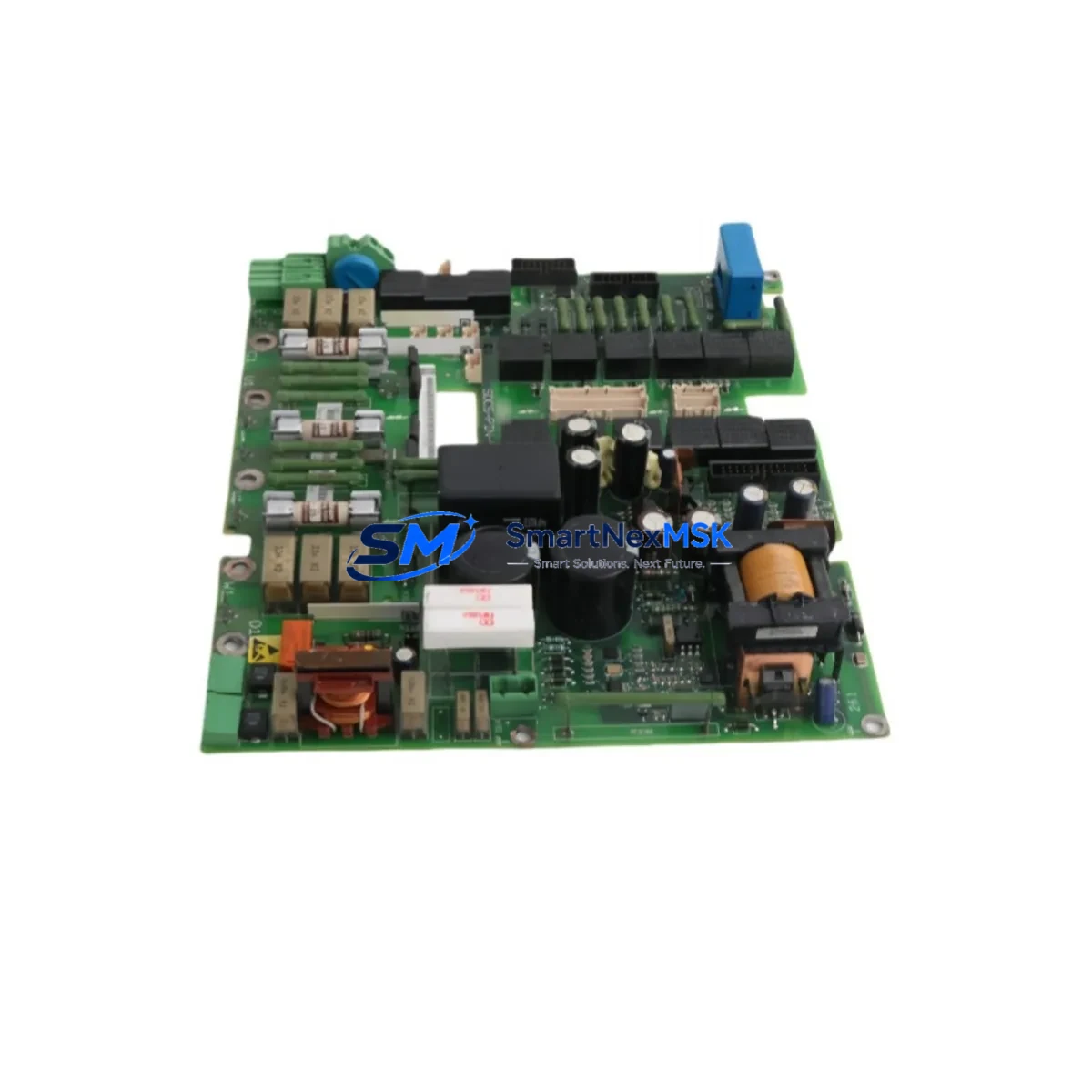
The ABB SDCS-PIN-4 (part number 3ADT314100R1001) is an original encoder feedback interface board designed for ABB DCS600 and DCS800 series DC drive systems. For maintenance engineers managing aging DC drive installations, this board is a critical spare that directly impacts motor speed feedback accuracy, closed-loop control stability, and overall drive availability. Unplanned failure of the encoder interface board can halt production lines within seconds — having a verified, tested replacement on the shelf is the most effective strategy for minimizing mean time to repair (MTTR).
The SDCS-PIN-4 interfaces between the incremental encoder mounted on the DC motor shaft and the main control board of the DCS drive. It conditions and transmits pulse signals that the drive uses for precise speed and position regulation. In high-cycle manufacturing environments — press lines, winding machines, extruders, and paper mills — encoder signal integrity is non-negotiable. A degraded or failed SDCS-PIN-4 typically manifests as erratic speed control, encoder fault codes (F-codes on the DCS800 panel), or complete drive trip. Maintenance teams familiar with the SDCS800 control board and SDCS-CON-4 converter control board will recognize that the encoder interface is often the first board to show wear in high-vibration or high-temperature cabinet environments.
Spare Maintenance Table
| Parameter | Specification |
|---|---|
| Part Number | SDCS-PIN-4 / 3ADT314100R1001 |
| Brand | ABB |
| Compatible Series | DCS600, DCS800 |
| Function | Encoder Feedback Interface Board |
| Encoder Input | Incremental TTL/HTL encoder signals |
| Supply Voltage | 24 VDC (from drive internal supply) |
| Mounting | Plug-in board, DCS drive control section |
| Origin | Germany |
| Operating Temperature | 0°C to +55°C |
| Application | DC motor speed/position feedback in industrial drives |
| Maintenance Recommendation | Inspect connector pins and encoder cable shielding at each planned shutdown; replace proactively every 5–8 years in high-cycle applications |
| Warranty | 12 Months |
| Condition | Original, tested before shipment |
Maintenance Planning for Continuous Operation
When scheduling a replacement of the SDCS-PIN-4, experienced maintenance engineers treat the intervention as an opportunity for a broader DCS drive cabinet inspection. The encoder interface board does not operate in isolation — its performance depends on the integrity of the entire signal chain and power supply environment.
Start by verifying the 24 VDC internal power supply rail that feeds the SDCS-PIN-4. A marginal power supply can cause intermittent encoder faults that are misdiagnosed as board failure. The SDCS-POW-4 power supply board, which provides regulated voltages to the DCS800 control section, should be checked for output ripple and capacitor condition during the same maintenance window.
Next, inspect the encoder cable and its shielding. Damaged or improperly grounded encoder cables are a leading cause of premature SDCS-PIN-4 failure. Replace any cable with cracked insulation or corroded connectors — use shielded twisted-pair cable rated for the encoder voltage level (TTL 5V or HTL 10–30V). At the same time, check the SDCS-CON-4 converter control board for any fault history logged in the drive event buffer, as recurring encoder faults may indicate a systemic issue rather than a single-board failure.
The SDCS-DSL-4 serial communication board and SDCS-COM-8 fieldbus adapter (if installed for PROFIBUS or DeviceNet integration) should also be visually inspected for loose connectors and corrosion. Communication faults during a drive restart after maintenance can delay recommissioning significantly. Similarly, check the SDCS-IOB-3 I/O extension board for any signs of terminal oxidation or loose wiring on analog and digital I/O channels connected to the process.
For drives operating in dusty or humid environments, inspect the cabinet door seals and internal fan filters. Contamination on the SDCS-PIN-4 connector edge and on the main backplane can cause high-resistance connections that mimic board failure. A compressed-air purge of the control section, combined with contact cleaner on the board edge connectors, is recommended before installing the replacement board.
Finally, verify the HMI or operator panel — typically an ACS/DCS Panel CDP312R — is displaying correct parameter values after the replacement. Re-enter any encoder pulses-per-revolution (PPR) parameter settings as required by the drive configuration, and confirm that the speed feedback signal matches the tachometer or reference speed during a no-load test run before returning the drive to production.
Site Replacement Workflow
Step 1 — Isolate and de-energize. Follow your site LOTO (Lockout/Tagout) procedure. Confirm that the DCS800 drive is fully de-energized and that the DC bus capacitors have discharged (typically 5 minutes after power-off). Do not work on the control section while the DC bus is live.
Step 2 — Document existing configuration. Before removing the SDCS-PIN-4, photograph the board position, connector orientation, and any parameter settings visible on the CDP312R panel. Upload the drive parameter file via DriveWindow or DriveStudio if a laptop connection is available. This step is critical for older DCS600 installations where parameter backup may not have been performed recently.
Step 3 — Remove the faulty board. Carefully unplug the encoder cable connector and any ribbon cable connections to the SDCS-PIN-4. Release the board retaining clips and slide the board out of its slot. Inspect the slot connector on the backplane for bent pins or debris before inserting the replacement.
Step 4 — Install the SDCS-PIN-4 3ADT314100R1001 replacement. Align the board with the guide rails and press firmly until the edge connector is fully seated. Reconnect all cables in the correct orientation. Verify that the encoder cable shield is grounded at the drive end only (single-point grounding) to prevent ground loops.
Step 5 — Power-up and verify. Restore power and observe the drive startup sequence. Check for any active fault codes on the CDP312R panel. Navigate to the encoder feedback parameter group and confirm that the PPR value matches the installed encoder. Run the drive at low speed (10–15% of rated speed) and verify that the speed feedback signal is stable and matches the speed reference. Gradually increase to full speed and confirm smooth, stable operation before returning to production.
This workflow applies equally to DCS600 legacy installations and current DCS800 systems, making the SDCS-PIN-4 3ADT314100R1001 a versatile spare that supports long-term system continuity across both platforms.
Spare Parts Support FAQ
Q1: Is the SDCS-PIN-4 3ADT314100R1001 compatible with both DCS600 and DCS800 drives?
The SDCS-PIN-4 is primarily designed for the DCS800 series. Compatibility with DCS600 depends on the specific hardware revision of your drive. Please provide your drive type code and hardware revision when ordering so our technical team can confirm compatibility before shipment.
Q2: How is the SDCS-PIN-4 tested before shipment?
Every unit undergoes functional verification on a test bench that simulates the DCS800 control section environment. Encoder signal input/output, power supply draw, and connector integrity are all checked. A test report is available upon request. All units are shipped with a 12-month warranty covering manufacturing defects and functional failure under normal operating conditions.
Q3: What is the recommended spare parts stocking strategy for DCS800 drives?
For critical production lines with DCS800 drives, we recommend stocking at minimum: one SDCS-PIN-4 encoder interface board, one SDCS-POW-4 power supply board, and one SDCS-CON-4 converter control board. This covers the three most common single-point failures in the DCS800 control section and enables same-shift recovery from most drive faults without waiting for emergency procurement.
Q4: What is the lead time and can you support long-term supply?
Standard in-stock orders ship within 1–3 business days. For customers requiring long-term supply agreements or bulk procurement for multi-drive installations, we offer scheduled delivery programs. Contact our team to discuss volume pricing and reserved stock arrangements that ensure supply continuity even as ABB transitions legacy DCS product lines.
© 2026 SMARTNEXMSK. All rights reserved.
Original Source: https://smartnexmsk.com
Contact: sales@smartnexmsk.com | +86 18259474341


