ABB SDCS-PIN-48-COAT 3ADT220090R0043 Retrofit-Ready Power Interface for DCS800 Control Systems
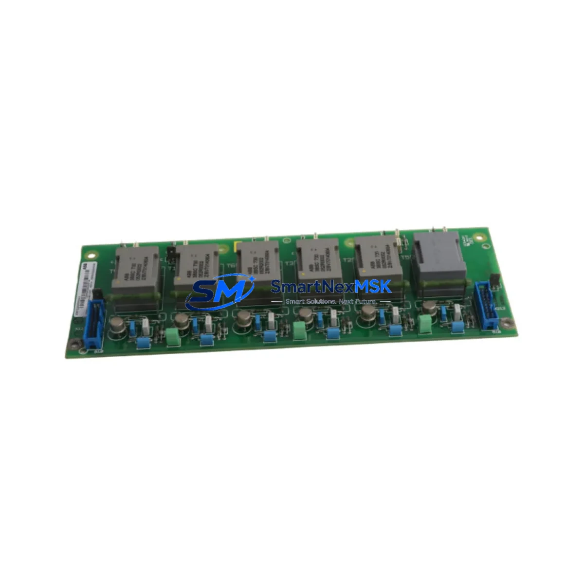
The ABB SDCS-PIN-48-COAT (part number 3ADT220090R0043) is a conformal-coated DC drive power interface board engineered for the ABB DCS800 series of DC drives. Designed to serve as a direct retrofit replacement for aging or discontinued power interface assemblies in legacy DC drive cabinets, this board bridges the gap between end-of-life drive hardware and modern automation infrastructure. Whether you are managing a planned upgrade cycle or responding to an unplanned failure on a critical production line, the SDCS-PIN-48-COAT delivers the electrical compatibility, mechanical fit, and firmware alignment required for a smooth, low-risk transition.
The conformal coating (COAT suffix) provides enhanced protection against humidity, condensation, and airborne contaminants — a critical requirement in paper mills, steel plants, chemical processing facilities, and marine environments where legacy DCS800 drives are commonly deployed. This makes the SDCS-PIN-48-COAT particularly well-suited for retrofit projects where the drive cabinet environment cannot be fully controlled during the changeover window.
Upgrade Compatibility Table
| Parameter | Details |
|---|---|
| Compatible Drive Series | ABB DCS800 (all frame sizes using SDCS-PIN-48 interface) |
| Replaces / Supersedes | SDCS-PIN-48 (non-coated variant), legacy DCS500 interface boards via adapter |
| Backplane Interface | 48-pin DIN connector; direct plug-in to DCS800 control section backplane |
| Installation Requirement | Power-off installation; torque settings per DCS800 Hardware Manual 3ADW000379 |
| Communication Compatibility | Compatible with SDCS-COM-8 (PROFIBUS), SDCS-COM-81 (DeviceNet), SDCS-COM-82 (Modbus RTU) |
| Firmware Alignment | Requires DCS800 firmware ≥ V7.x; verify via DriveWindow Light 2 before commissioning |
| Replacement Recommendation | Direct drop-in replacement; no parameter re-mapping required for standard configurations |
| Commissioning Focus | Verify armature current feedback scaling, field current reference, and speed feedback source after swap |
| Warranty | 12-Month Warranty — covers manufacturing defects and functional failure under normal operating conditions |
Retrofit Planning for Existing Automation Systems
A successful retrofit of the SDCS-PIN-48-COAT into an existing DCS800 installation begins well before the physical swap. Engineers should start by auditing the full drive cabinet bill of materials. In a typical DCS800 cabinet, the power interface board works in close coordination with the SDCS-CON-F control board, the SDCS-FEX-2 field excitation module, and the SDCS-DSL-4 digital speed feedback board. Any of these companion boards that are approaching end-of-life should be evaluated for simultaneous replacement to avoid a second unplanned outage shortly after the initial retrofit.
Terminal wiring adaptation is a key step. The SDCS-PIN-48-COAT uses the same X1 and X2 terminal block layout as the standard SDCS-PIN-48, so existing field wiring for armature voltage feedback, thermistor inputs, and auxiliary power supply connections can typically be reused without modification. However, engineers should verify wire gauge compatibility and re-torque all terminal connections to the values specified in the DCS800 wiring diagram, as loose connections are a leading cause of post-retrofit nuisance trips.
For sites running the DCS800 in a multi-drive configuration — for example, a coordinated DC drive line with a master drive and several follower drives — the retrofit plan must account for the SDCS-COM-8 PROFIBUS adapter or SDCS-COM-82 Modbus RTU module that handles inter-drive communication. These communication modules mount directly onto the SDCS-PIN-48-COAT and must be transferred carefully from the old board to the new one, with the fieldbus node address and baud rate settings verified against the existing network configuration before the drive is re-energized.
Sites that use an ABB ACS800 or ACS880 as the upstream process controller feeding speed references to the DCS800 via analog or fieldbus links should confirm that the analog I/O scaling parameters (Group 13 in the DCS800 parameter set) remain intact after the board swap. If the drive’s parameter memory is stored on the SDCS-CON-F control board rather than on the PIN board itself, parameters will survive the swap automatically — but this should be confirmed before work begins by checking parameter 9.04 (Parameter Save) in DriveWindow.
HMI integration is another area requiring attention. Plants using an ABB CP600 or third-party HMI panel connected via Modbus RTU should verify that the drive’s station address and communication timeout settings are unchanged after the retrofit. A brief HMI communication test — cycling through all drive status words and command words — should be performed before handing the line back to production.
Finally, for sites where the DCS800 is housed in an ABB ACS800 MNS or similar motor control center (MCC) with a shared DC bus, the retrofit window should be coordinated with the MCC’s bus protection relay settings to ensure that the bus does not trip during the drive’s initial power-up sequence after the board replacement.
Downtime Control During System Migration
Minimizing production downtime during a power interface board replacement on a live DC drive system requires a structured, pre-tested approach. The recommended sequence is as follows:
1. Pre-work parameter backup. Before any hardware is touched, connect a laptop running DriveWindow Light 2 to the DCS800’s RS-232 service port and perform a full parameter upload. Save the parameter file with a timestamp and the drive tag number. This backup is your insurance policy — if the replacement board behaves unexpectedly, you can restore the exact parameter set within minutes rather than hours.
2. Photograph and label all wiring. Even though the SDCS-PIN-48-COAT uses the same terminal layout as its predecessor, field wiring in older cabinets is often non-standard. Photograph every terminal block and connector before disconnection. Label each wire with its terminal designation using heat-shrink markers.
3. Controlled power-down sequence. Follow the DCS800 Hardware Manual shutdown sequence: ramp the motor to zero speed, disable the drive via the Run Enable input, open the main contactor, and then isolate the auxiliary 24 VDC supply before removing the board. This sequence protects the armature circuit and prevents residual field current from damaging the new board during installation.
4. Board swap and initial power-up. Install the SDCS-PIN-48-COAT, reconnect all terminals, and restore power in reverse order. On first power-up, the drive will perform a self-test. Monitor the drive’s fault log via the panel or DriveWindow for any F-codes (fault codes) that indicate wiring errors or parameter mismatches.
5. Functional verification before production restart. Run the motor at reduced speed (typically 10–20% of rated speed) in local control mode before switching back to remote/fieldbus control. Verify speed feedback, current feedback, and field current readings against the pre-retrofit baseline. Only after this verification is complete should the line be returned to automatic production control.
With proper preparation, the physical swap and recommissioning of a DCS800 power interface board can typically be completed within a 4–6 hour planned maintenance window, keeping unplanned production loss to an absolute minimum.
Retrofit Support FAQ
Q1: Is the SDCS-PIN-48-COAT a direct replacement for the standard SDCS-PIN-48?
Yes. The SDCS-PIN-48-COAT is functionally identical to the SDCS-PIN-48 but adds conformal coating for enhanced environmental protection. It is a direct drop-in replacement with no hardware or parameter changes required. Both boards share the same 48-pin backplane connector and terminal block layout.
Q2: Can this board be used to upgrade a DCS500 series drive to DCS800?
The SDCS-PIN-48-COAT is designed for the DCS800 platform and is not directly compatible with DCS500 hardware. A DCS500-to-DCS800 migration requires a full drive replacement, including the control section, power section, and field excitation module. However, in many cases the existing motor, transformer, and cabinet wiring can be reused, significantly reducing the total retrofit cost. Contact our technical team for a migration feasibility assessment.
Q3: What commissioning steps are required after installing the SDCS-PIN-48-COAT?
After installation, restore the parameter backup via DriveWindow Light 2 and verify the following: armature current feedback scaling (parameter group 4), field current reference and feedback (parameter group 3), speed feedback source and scaling (parameter group 5), and communication module node address (parameter group 51 for PROFIBUS or group 52 for Modbus). Perform a no-load motor run at reduced speed before returning to full production. All boards supplied by SMARTNEXMSK are pre-tested and shipped with a functional test report.
Q4: What does the 12-month warranty cover?
All SDCS-PIN-48-COAT boards supplied by SMARTNEXMSK carry a 12-month warranty covering manufacturing defects and functional failure under normal operating conditions. The warranty period begins from the date of shipment. Boards that fail due to incorrect installation, overvoltage events, or physical damage are not covered. In the event of a warranty claim, SMARTNEXMSK will provide a replacement board within 5 business days after receipt and inspection of the returned unit. Each board is individually tested prior to shipment to verify electrical functionality.
© 2026 SMARTNEXMSK. All rights reserved.
Original Source: https://smartnexmsk.com
Contact: sales@smartnexmsk.com | +86 18259474341


