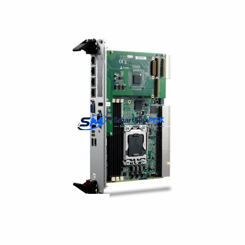
Adlink CPCI-6920/S408/M4G(G)-1270 Spare for CompactPCI Automation
The Adlink CPCI-6920/S408/M4G(G)-1270 is a 6U CompactPCI Single Board Computer built around the Intel Core i7-1270 processor with 4 GB DDR4 ECC RAM and a 256 GB solid-state storage module. Designed for mission-critical industrial automation, SCADA, machine vision, and process control platforms, this SBC serves as the computational backbone of CompactPCI chassis deployed across manufacturing lines, power utilities, railway signalling, and defence-grade test systems. When this board fails or reaches end-of-service life, the entire control system is at risk of unplanned downtime — making a verified, maintenance-ready spare an essential element of any responsible spare-parts strategy.
SMARTNEXMSK supplies the CPCI-6920/S408/M4G(G)-1270 as an original Adlink unit, individually tested prior to shipment, and backed by a 12-month warranty. Each board is verified for BIOS integrity, memory channel operation, PCIe lane continuity, and rear I/O functionality before leaving our facility. Fast global dispatch ensures that maintenance engineers can restore system operation with minimal delay.
Spare Maintenance Table
| Parameter | Specification |
|---|---|
| SKU / Part Number | CPCI-6920/S408/M4G(G)-1270 |
| Brand | Adlink Technology |
| Series | CPCI-6920 |
| Form Factor | 6U CompactPCI (PICMG 2.0 R3.0) |
| Processor | Intel Core i7-1270 (12-core, up to 4.8 GHz) |
| Memory | 4 GB DDR4 ECC SO-DIMM (expandable) |
| Storage | 256 GB M.2 SSD (industrial grade) |
| Operating System Support | Windows 10 IoT, Linux (kernel 5.x+), VxWorks |
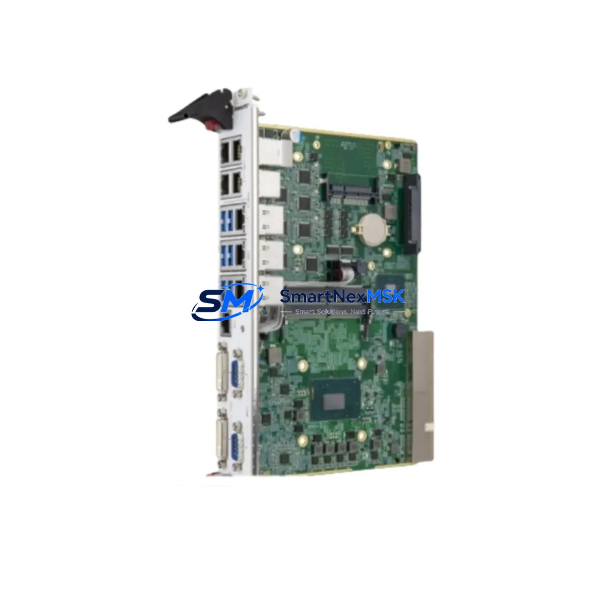
| Rear I/O | GbE ×2, USB 3.2 ×4, COM ×2, DIO, PCIe x4 |
| Power Input | +5 V / +3.3 V / ±12 V via CompactPCI backplane |
| Operating Temperature | 0 °C to +60 °C (standard); –40 °C to +85 °C (extended option) |
| Humidity | 5 % to 95 % RH, non-condensing |
| Vibration / Shock | IEC 60068-2-6 / IEC 60068-2-27 compliant |
| Compatibility | Adlink CPCI-6920 series chassis; PICMG 2.0 R3.0 backplanes |
| Certifications | CE, FCC Class A, RoHS |
| Origin | Taiwan |
| Warranty | 12 Months (SMARTNEXMSK) |
| Condition | Original, New / Refurbished-Tested (specify at order) |
| Lead Time | In-stock: 1–3 business days; sourced: 5–10 business days |
Maintenance Planning for Continuous Operation
Replacing the CPCI-6920/S408/M4G(G)-1270 in a live control cabinet is rarely an isolated task. Maintenance engineers and procurement teams should treat this SBC replacement as an opportunity to audit the surrounding subsystems and pre-empt secondary failures that often surface after a board swap.
Begin with the CompactPCI backplane itself — inspect connector pins for oxidation, verify slot keying, and confirm that the backplane power rails deliver stable +5 V and +3.3 V within ±5 % tolerance. A degraded backplane can damage a new SBC within hours of installation. Alongside the backplane, inspect the CPCI-6920 chassis power supply module: measure output ripple and confirm that the hold-up time meets the system’s ride-through requirement during brief mains interruptions.
Next, review the Adlink CPCI-6910 or CPCI-6930 peripheral slot cards installed in the same chassis — these I/O expansion boards share the same backplane bus and are subject to the same thermal and vibration stresses as the SBC. If the CPCI-6920 has failed due to thermal runaway, the adjacent I/O cards may have sustained latent damage. Similarly, check any installed Adlink CPCI-COM232I or CPCI-COM422I serial communication modules for correct baud-rate configuration and cable integrity after the board replacement.
For systems interfacing with field devices, inspect the terminal block assemblies and DIN-rail mounted signal isolators connected to the SBC’s rear I/O panel. Faulty isolation on 4–20 mA analogue loops or thermocouple inputs can introduce ground loops that corrupt process data and accelerate SBC failure. If the system uses Adlink PCI-7230 or PCI-7250 digital I/O cards in a companion rack, verify relay contact resistance and optocoupler response times as part of the same maintenance window.
Where the CPCI-6920 communicates with a PROFIBUS DP or EtherCAT master card, confirm that the network topology, node addresses, and cycle times are correctly restored after the SBC image is reloaded. Communication timeouts are a common post-replacement fault that can be mistaken for a hardware defect. Finally, check the UPS module or battery-backed power conditioner supplying the CompactPCI chassis — a weak battery that failed to protect the previous SBC during a power event is likely to repeat the failure on the replacement unit.
Stocking a minimum of one spare CPCI-6920/S408/M4G(G)-1270 alongside a spare chassis power supply, one I/O expansion card, and a set of pre-configured compact flash or SSD images is the recommended baseline for facilities operating more than two CPCI-6920 chassis. This approach reduces mean time to repair (MTTR) from days to hours.
Site Replacement Workflow
Step 1 — Pre-replacement preparation: Back up the current SBC image to a network share or USB drive. Document the BIOS settings, boot sequence, IP addresses, and any hardware jumper or DIP-switch configurations. Photograph the rear I/O cable routing before disconnection.
Step 2 — Safe isolation: Follow site LOTO (Lockout/Tagout) procedures. De-energise the CompactPCI chassis and wait for capacitor discharge (minimum 30 seconds after power-off). Verify zero-energy state with a calibrated multimeter before opening the chassis.
Step 3 — Board extraction: Release the front-panel ejector levers simultaneously to avoid connector damage. Slide the CPCI-6920 board straight out along the card guides. Place the removed board in an ESD-protective bag immediately.
Step 4 — Replacement installation: Inspect the replacement CPCI-6920/S408/M4G(G)-1270 for shipping damage. Confirm the SSD image version matches the system requirement. Slide the board into the correct slot, engage ejector levers, and torque front-panel screws to the chassis specification.
Step 5 — Reconnection and power-up: Reconnect all rear I/O cables in the documented sequence. Restore power and observe POST indicators. Confirm OS boot, network connectivity, and process application startup before releasing the system to production.
Step 6 — Functional verification: Run a 30-minute burn-in cycle under normal process load. Monitor CPU temperature, memory ECC error counters, and network packet loss. Log the replacement in the site maintenance management system (CMMS) with the new board serial number and warranty expiry date.
This workflow is compatible with direct replacement of earlier CPCI-6920 variants equipped with previous-generation Intel Core processors, provided the SSD image is updated to support the i7-1270 hardware platform. No chassis or backplane modifications are required for in-series substitution.
Spare Parts Support FAQ
Q1: Is the CPCI-6920/S408/M4G(G)-1270 a direct drop-in replacement for older CPCI-6920 variants?
A: Yes, within the CPCI-6920 series the mechanical form factor and backplane connector pinout are preserved across processor generations. However, the SSD operating system image must be updated to include drivers for the Intel Core i7-1270 platform. SMARTNEXMSK can supply pre-configured SSD images upon request.
Q2: What pre-shipment testing does SMARTNEXMSK perform on each unit?
A: Every CPCI-6920/S408/M4G(G)-1270 is powered on and subjected to a full POST cycle, memory stress test (MemTest86+), SSD read/write verification, and rear I/O port continuity check before packaging. A test report is available upon request. Units are shipped in ESD-protective packaging with anti-vibration foam inserts.
Q3: How should this SBC be managed within a long-term spare-parts inventory strategy?
A: For facilities with three or more CPCI-6920 chassis in service, we recommend maintaining at least one cold-spare SBC and one pre-imaged SSD. Boards in storage should be kept in ESD bags inside a climate-controlled environment (15–25 °C, <60 % RH) and powered on for a 2-hour functional check every 12 months. SMARTNEXMSK offers long-term supply agreements to guarantee availability beyond the standard product lifecycle.
Q4: What is covered under the 12-month warranty?
A: The 12-month warranty covers manufacturing defects, component failure under normal operating conditions, and DOA (Dead on Arrival) replacement. It does not cover damage resulting from incorrect installation, overvoltage, ESD mishandling, or unauthorised modification. Warranty claims are processed within 5 business days of receipt of the returned unit.
© 2026 SMARTNEXMSK. All rights reserved.
Original Source: https://smartnexmsk.com
Contact: sales@smartnexmsk.com | +86 18259474341