Allen-Bradley 1336T-GT1-SP34B Spare for 1336 PLUS II Automation: Spare Replacement & Industrial Downtime Risk Control
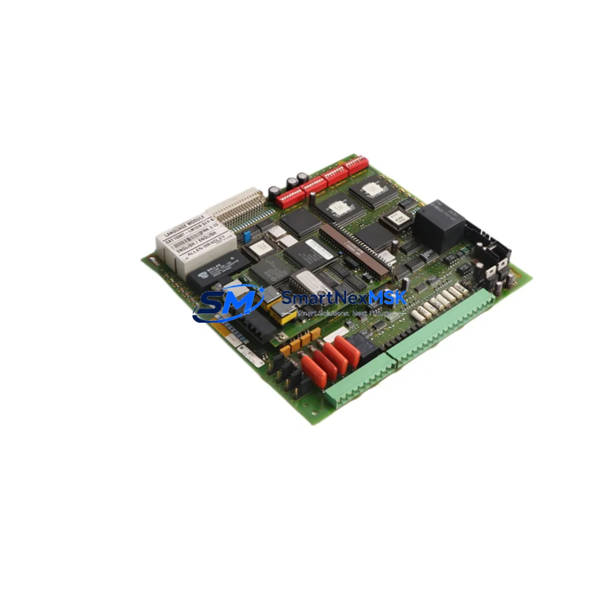
The Allen-Bradley 1336T-GT1-SP34B is an original gate driver control board engineered for the 1336 PLUS II series of AC variable frequency drives. As a critical power electronics interface between the drive’s control logic and its IGBT output stage, this board governs switching signals, fault detection, and thermal protection — making it one of the highest-priority spare components in any 1336 PLUS II-based motor control system. Whether you are managing a continuous process line, a pump station, or a conveyor automation cell, an unplanned failure of this board can result in immediate drive shutdown and extended production downtime.
This listing covers the original spare part with part numbers 74101-954-52C and 74103-015-52A, cross-referenced against the 1336T-LM1EN main control board platform. Each unit is sourced from verified supply channels, functionally tested prior to dispatch, and backed by a 12-month warranty. Fast worldwide shipping is available to support emergency replacement requirements.
Spare Maintenance Table
| Parameter | Specification / Detail |
|---|---|
| Part Number | 1336T-GT1-SP34B |
| Cross Reference | 74101-954-52C / 74103-015-52A |
| Compatible Platform | Allen-Bradley 1336 PLUS II AC Drive Series |
| Board Function | IGBT Gate Driver & Fault Isolation Control |
| Voltage Class | Compatible with 200–600 VAC drive variants (series-dependent) |
| Interface | Ribbon/connector interface to 1336T-LM1EN main control board |
| Thermal Protection | Integrated overcurrent and thermal fault signaling |
| Installation | Direct board-level replacement; no firmware programming required |
| Application Environment | Industrial panel, MCC cabinet, pump/fan/conveyor automation |
| Condition | Original spare — tested before shipment |
| Warranty | 12 Months from date of shipment |
| Origin | USA (Allen-Bradley / Rockwell Automation) |
| Weight | 480 g (approx.) |
Maintenance Planning for Continuous Operation
When a 1336T-GT1-SP34B gate driver board fails or is flagged during a scheduled inspection, experienced maintenance engineers know that the fault rarely exists in isolation. A gate driver failure is often preceded or accompanied by stress on adjacent components in the same power conversion circuit. A thorough site assessment should include the following checks before and after board replacement:
Begin with the 1336T-LM1EN main control board, which communicates directly with the gate driver via the internal ribbon interface. Inspect for corrosion, connector damage, or firmware fault codes that may have triggered the gate driver fault in the first place. Next, verify the DC bus capacitor bank — capacitor degradation is a leading cause of gate driver overstress in aging 1336 PLUS II drives. Check capacitance values and ESR if test equipment is available.
Inspect the IGBT power module for signs of thermal damage or gate-emitter short circuits, as a shorted IGBT can destroy a replacement gate driver board within seconds of power-up if not identified first. The 24 VDC internal power supply board should also be tested — low or noisy auxiliary voltage is a common root cause of gate driver logic faults and erratic switching behavior.
For drives installed in motor control centers, check the 1336-MOD-L2E or equivalent communication module for DeviceNet or DH+ connectivity faults that may have masked the underlying hardware issue. Review the 1336-BRF series dynamic braking resistor module if the application involves frequent deceleration cycles — excessive braking energy can elevate DC bus voltage and stress the gate driver circuit.
On the I/O side, inspect the 1336T-B series I/O expansion board for loose terminal connections or signal wiring faults that could cause spurious fault trips. Verify the integrity of shielded signal cables between the drive and the PLC or DCS controller — unshielded or damaged cables introduce noise that can corrupt gate timing signals. If the drive is part of a larger Rockwell Automation system, confirm that the 1756-series ControlLogix I/O modules or 1769-series CompactLogix I/O modules are reporting correct drive status and that no upstream logic faults are present.
Finally, inspect the control cabinet thermal management system — cabinet fans, filter mats, and heat exchanger units. Elevated ambient temperature inside the enclosure accelerates gate driver aging and is one of the most overlooked factors in recurring drive failures. Replacing the 1336T-GT1-SP34B without addressing thermal management will shorten the service life of the new board.
Site Replacement Workflow
Step 1 — Isolation & Lockout: De-energize the drive, apply LOTO (Lockout/Tagout) procedure, and wait a minimum of 5 minutes for DC bus capacitors to discharge. Verify bus voltage with a calibrated meter before opening the drive enclosure.
Step 2 — Fault Code Documentation: Before removing the faulty board, record all active and historical fault codes from the 1336 PLUS II HIM (Human Interface Module) or via DriveExplorer/DriveExecutive software. This data is essential for root cause analysis and warranty documentation.
Step 3 — Board Removal: Disconnect the ribbon cable and any auxiliary connectors from the 1336T-GT1-SP34B. Note the orientation and routing of all cables before removal. Use an ESD wrist strap throughout the procedure.
Step 4 — Visual Inspection of Mounting Area: Inspect the drive chassis for burn marks, contamination, or mechanical damage that may indicate the failure mode. Clean the mounting area before installing the replacement board.
Step 5 — Installation of Replacement Board: Install the new 1336T-GT1-SP34B, reconnect all cables in the correct orientation, and verify connector seating. No parameter programming is required — the gate driver board does not store drive parameters.
Step 6 — Power-Up & Functional Test: Re-energize the drive and monitor for fault codes during the first power-up sequence. Run the motor at low speed under no-load conditions before returning the drive to full production duty. Confirm that output current waveforms are symmetrical across all three phases.
Step 7 — Documentation & Spare Stock Update: Record the replacement in the maintenance log, update the spare parts inventory, and order a replacement unit to restore buffer stock. For critical production lines, maintaining at least one 1336T-GT1-SP34B in local spare stock is strongly recommended.
Spare Parts Support FAQ
Q1: Is the 1336T-GT1-SP34B compatible with all 1336 PLUS II drive ratings?
The 1336T-GT1-SP34B is designed for specific power and voltage variants within the 1336 PLUS II series. Compatibility is determined by the drive’s catalog number and power rating. Please provide your full drive catalog number when ordering to confirm compatibility. Our technical team can cross-reference your drive’s BOM to verify the correct gate driver variant before shipment.
Q2: What testing is performed before shipment?
Each 1336T-GT1-SP34B unit undergoes functional verification prior to dispatch, including gate signal integrity checks and visual inspection for component damage. Units are packed in ESD-safe packaging with desiccant to prevent moisture ingress during transit. A test report is available upon request for critical applications.
Q3: What does the 12-month warranty cover?
The 12-month warranty covers manufacturing defects and functional failures under normal operating conditions from the date of shipment. It does not cover damage resulting from incorrect installation, overvoltage events, or failure to address root-cause faults (such as a shorted IGBT) prior to installing the replacement board. Warranty claims are processed with return shipment support.
Q4: Can you supply the 1336T-GT1-SP34B on an ongoing basis for long-term maintenance contracts?
Yes. We maintain stock of 1336 PLUS II spare components to support long-term maintenance programs and MRO procurement contracts. For facilities managing multiple 1336 PLUS II drives, we offer priority allocation and consignment stock arrangements. Contact our team to discuss volume pricing and supply continuity agreements for your site’s spare parts program.
© 2026 SMARTNEXMSK. All rights reserved.
Original Source: https://smartnexmsk.com
Contact: sales@smartnexmsk.com | +86 18259474341


