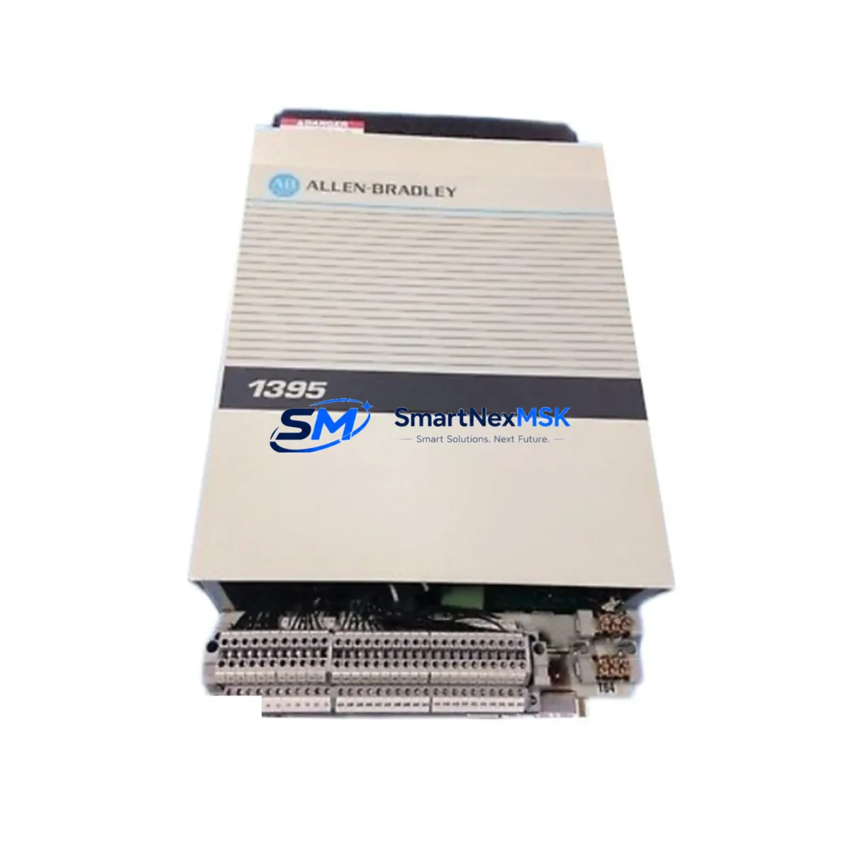
Allen-Bradley 1395-A65N-C1-PZ Retrofit DC Drive, 1395 Series: Compatible Modernization for Legacy Control Systems
The Allen-Bradley 1395-A65N-C1-PZ is a 65-ampere DC variable speed drive engineered for the 1395 Series control platform. As original 1395 Series drives approach end-of-life and spare parts become increasingly scarce, the 1395-A65N-C1-PZ remains one of the most sought-after retrofit and replacement units for facilities operating legacy DC motor control systems in manufacturing, material handling, paper, metals, and process industries. SMARTNEXMSK maintains verified stock of this unit, fully tested and backed by a 12-month warranty, ready to ship to minimize your unplanned downtime.
Whether you are executing a planned upgrade of an aging control cabinet, responding to an emergency drive failure, or migrating a legacy DC drive system toward a more maintainable architecture, the 1395-A65N-C1-PZ provides a direct-fit solution that preserves your existing motor wiring, terminal block layout, and backplane interface — reducing re-engineering time and commissioning risk on the plant floor.
Upgrade Compatibility Table
| Parameter | Specification / Recommendation |
|---|---|
| SKU / Part Number | 1395-A65N-C1-PZ |
| Series Compatibility | Allen-Bradley 1395 Series DC Variable Speed Drives |
| Output Current Rating | 65 A continuous DC output |
| Mounting / Form Factor | Direct chassis replacement; verify enclosure depth and DIN rail clearance before installation |
| Terminal Wiring Compatibility | Compatible with standard 1395 Series terminal block assignments; confirm TB1/TB2 wiring map against existing drawings |
| Communication Interface | Supports 1395 Series native I/O interface; verify Remote I/O (RIO) adapter configuration if DH+ or DeviceNet adapters are present |
| Replacement Scope | Drop-in retrofit for discontinued 1395-A65N variants; confirm firmware revision compatibility with host PLC program |
| Commissioning Notes | Re-enter drive parameters (speed reference scaling, current limits, accel/decel ramps) after replacement; do not assume parameter retention |
| Warranty | 12-Month Warranty — covers manufacturing defects and functional failure under normal operating conditions |
| Pre-Shipment Testing | Each unit undergoes functional power-on and output verification before dispatch |
Retrofit Planning for Existing Automation Systems
A successful 1395-A65N-C1-PZ retrofit begins well before the replacement unit arrives on site. Engineers and maintenance teams should pull the original control cabinet drawings and verify the power supply capacity feeding the drive — the 1395 Series requires a correctly rated AC input supply, and an undersized transformer or fused disconnect will cause nuisance trips immediately after commissioning. Confirm that the existing 1395 Series power supply module (such as the 1395-PS or equivalent internal supply board) is in serviceable condition, as a failing supply is frequently the root cause of drive faults rather than the drive board itself.
Terminal block wiring is the next critical checkpoint. The 1395-A65N-C1-PZ uses the standard 1395 Series TB1 and TB2 terminal assignments for analog speed reference, digital I/O, and motor feedback signals. Before disconnecting the old unit, photograph and document every wire termination. Pay particular attention to the tachometer feedback wiring if the system uses a DC tachogenerator for closed-loop speed regulation — incorrect tach polarity will cause the drive to run away at startup.
If the host controller is an Allen-Bradley PLC-5 or SLC 500 communicating to the drive via a 1771-ASB Remote I/O adapter or a 1203-GD1 DeviceNet communications module, verify that the node address and baud rate settings on the replacement drive match the original configuration exactly. A mismatch here will cause the PLC program to fault on I/O loss, and the HMI — whether a PanelView 550, PanelView 900, or a third-party operator panel — will display drive fault alarms until communication is restored. Update the HMI tag database if any drive parameter addresses have shifted between firmware revisions.
For systems that include 1771 I/O chassis with analog output modules providing the speed reference signal to the drive, confirm that the analog output scaling in the PLC program (typically 0–10 VDC or 4–20 mA) matches the drive’s speed reference input configuration. Mismatched scaling results in incorrect motor speed at full command output. Similarly, if the system uses a 1336 PLUS or 1336 IMPACT drive elsewhere in the same control cabinet for a different axis, ensure that the 1395 replacement does not share a common DC bus configuration that would require coordinated parameter changes across both drives.
Backplane and rack considerations apply when the 1395 drive is mounted in a 1771 I/O chassis alongside other modules. Verify slot addressing and ensure the chassis backplane is not damaged — a cracked or corroded backplane connector will cause intermittent communication faults that are difficult to diagnose after the new drive is installed. If the system includes a 1785-L40B or 1785-L80B PLC-5 processor as the master controller, confirm that the processor’s I/O configuration table correctly maps to the 1395 drive’s logical address before going live.
Downtime Control During System Migration
Minimizing production downtime during a 1395-A65N-C1-PZ replacement requires a structured pre-outage preparation protocol. Before the scheduled maintenance window, upload and save a copy of the host PLC program from the 1785 or SLC 500 processor using RSLogix 5 or RSLogix 500 — never assume the processor memory is intact after a drive fault event, as power disturbances during a drive failure can corrupt processor memory in older systems. Store the program backup on a dedicated programming laptop and a secondary USB drive.
Document all drive parameters from the existing 1395-A65N-C1-PZ using the 1395 Series HIM (Human Interface Module) or via the DriveExplorer software tool if a 1203-series DPI communications adapter is present. Key parameters to record include: maximum speed reference, minimum speed clamp, current limit setpoint, accel and decel time constants, IR compensation, and any custom fault response configurations. These values must be re-entered into the replacement drive during commissioning — the 1395 Series does not support automatic parameter cloning between units without a dedicated parameter transfer tool.
During the physical swap, use insulated tools and follow LOTO (Lockout/Tagout) procedures rigorously. After installing the 1395-A65N-C1-PZ, perform a no-load power-on test before reconnecting the motor leads — verify that the drive powers up without fault codes, that the keypad or HIM displays correctly, and that the communication link to the PLC is established. Only then reconnect the motor and perform a slow-speed jog test to confirm correct rotation direction and tachometer feedback polarity before returning the system to automatic control mode.
For facilities that cannot tolerate any unplanned extension of the maintenance window, SMARTNEXMSK recommends maintaining a pre-configured spare 1395-A65N-C1-PZ with parameters pre-loaded, stored in a climate-controlled cabinet adjacent to the control panel. This hot-spare strategy reduces the replacement window to under 30 minutes for experienced maintenance personnel.
Retrofit Support FAQ
Q1: Is the 1395-A65N-C1-PZ a direct drop-in replacement for all 1395-A65N variants?
The 1395-A65N-C1-PZ is compatible with the standard 1395-A65N mounting footprint and terminal assignments. However, suffix codes (such as -C1 and -PZ) denote specific option configurations including control board revision and protective coating. Confirm your original unit’s suffix against the replacement to ensure full functional equivalence. If your original unit carried a different suffix, contact our technical team — in most cases the -C1-PZ variant is functionally interchangeable, but parameter adjustments may be required.
Q2: What commissioning steps are required after installing the replacement drive?
After physical installation and wiring verification, power on the drive and confirm no fault codes are present. Re-enter all drive parameters documented from the original unit. Perform a no-load test followed by a slow-speed jog with the motor connected. Verify tachometer feedback polarity, speed reference scaling, and PLC communication link status before returning to automatic operation. Allow the drive to run at full load for a minimum of 30 minutes and monitor for thermal faults or current limit trips before signing off on the replacement.
Q3: Can the 1395-A65N-C1-PZ communicate with a ControlLogix or CompactLogix PLC?
The 1395 Series was designed for integration with PLC-5 and SLC 500 platforms via Remote I/O or DeviceNet. Direct native communication with ControlLogix or CompactLogix processors requires a 1203-GD1 DeviceNet scanner or a 1747-SDN DeviceNet scanner module in the SLC chassis acting as a bridge. If your facility is migrating from a PLC-5 to a ControlLogix 1756-L7x or 1756-L8x platform, plan for the communication adapter configuration as part of the migration scope.
Q4: What does the 12-month warranty cover, and what is the claims process?
The 12-month warranty covers manufacturing defects and functional failure under normal operating conditions from the date of shipment. It does not cover damage resulting from incorrect installation, overvoltage events, water ingress, or unauthorized modification. To initiate a warranty claim, contact sales@smartnexmsk.com with your order number, a description of the fault symptom, and any fault codes displayed. Our technical team will assess the claim and arrange for replacement or repair within 5 business days of receiving the returned unit.
© 2026 SMARTNEXMSK. All rights reserved.
Original Source: https://smartnexmsk.com
Contact: sales@smartnexmsk.com | +86 18259474341


