Allen-Bradley 1440-SCDB9FXM2 Maintenance-Ready Spare XM Series: Spare Replacement & Industrial Downtime Risk Control
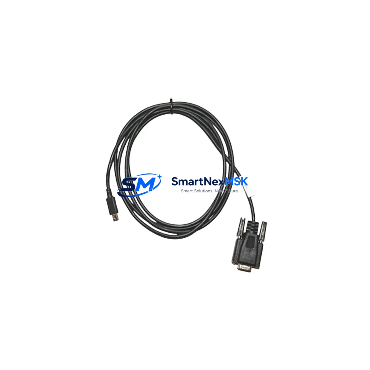
The Allen-Bradley 1440-SCDB9FXM2 is an original DB9 serial communication cable engineered for the XM Series condition monitoring platform by Rockwell Automation. In industrial maintenance environments — from rotating machinery protection to vibration analysis panels — this cable serves as the critical data link between XM Series modules and configuration or monitoring interfaces. When this cable degrades, becomes intermittent, or fails entirely, the entire condition monitoring loop is compromised, leaving rotating assets unprotected and maintenance engineers blind to early fault signatures.
Stocking the 1440-SCDB9FXM2 as a verified spare eliminates the most common cause of extended downtime in XM-based monitoring systems: the inability to re-establish communication between the XM module and the host PC or HMI during a fault investigation or firmware update. Every maintenance-ready spare program for XM Series installations should include this cable alongside the core module inventory.
Spare Maintenance Table
| Parameter | Specification / Detail |
|---|---|
| Part Number | 1440-SCDB9FXM2 |
| Brand | Allen-Bradley / Rockwell Automation |
| Series | XM Series Condition Monitoring |
| Cable Type | DB9 Serial Communication Cable |
| Connector Interface | DB9 Female to XM Module Port |
| Application | XM Series module configuration, firmware update, serial data link |
| Compatible Modules | 1440-VST02-01RA, 1440-TBS02-01RB, 1440-SPD02-01RA and compatible XM Series variants |
| Origin | United States (Original Rockwell Automation) |
| Installation Environment | Control cabinet, panel-mount, industrial floor |
| Maintenance Role | Communication restoration, module configuration, field diagnostics |
| Pre-shipment Testing | Continuity and signal integrity verified before dispatch |
| Warranty | 12 Months from date of shipment |
| Lead Time | In-stock, ships within 1–3 business days |
Maintenance Planning for Continuous Operation
When a maintenance or reliability engineer responds to a communication fault on an XM Series condition monitoring system, the 1440-SCDB9FXM2 cable is rarely the only component requiring inspection. A structured spare parts review should accompany any cable replacement to prevent repeat failures and ensure the monitoring loop is fully restored.
Begin with the XM Series module itself — units such as the 1440-VST02-01RA vibration module or the 1440-TBS02-01RB temperature/speed module should be checked for firmware currency and internal diagnostics before assuming the cable is the sole fault source. Inspect the 24 VDC power supply feeding the XM rack; an unstable supply voltage is a common root cause of intermittent communication errors that are misdiagnosed as cable faults.
The 1492-CABLE series terminal block wiring and field wiring terminations at the XM module’s I/O connectors should be verified for tightness and insulation integrity, particularly in high-vibration environments. If the XM system communicates upstream via DeviceNet or EtherNet/IP, inspect the corresponding network adapter module — such as the 1440-ACNR DeviceNet adapter — for fault indicators and connection integrity.
For installations where the XM system feeds data to a ControlLogix or CompactLogix PLC, verify the backplane communication between the XM gateway module and the processor. The 1756-EN2T EtherNet/IP communication module or equivalent should be checked for dropped packet counts. Signal isolators and 4–20 mA signal conditioners in the vibration or temperature signal chain should also be inspected, as degraded isolation can introduce noise that triggers false communication timeouts.
At the HMI level, if the XM system is monitored via a PanelView Plus terminal, verify the RS-232 or Ethernet connection from the HMI to the XM gateway. Fuse holders and miniature circuit breakers protecting the 24 VDC rail should be tested for continuity. Finally, review the DIN rail terminal blocks (such as 1492-W3 or equivalent) used for field sensor wiring — loose terminations at these points are a frequent source of intermittent signal loss that can be confused with cable or module failure.
Site Replacement Workflow
Replacing the 1440-SCDB9FXM2 in the field is a straightforward procedure, but it must be executed with care to avoid introducing new faults or extending downtime beyond the cable swap itself.
Step 1 — Isolate and document: Before disconnecting the existing cable, document the current module configuration using RSLogix 5000 or Studio 5000 if accessible. Note any active fault codes displayed on the XM module’s LED indicators.
Step 2 — Power state: The 1440-SCDB9FXM2 can typically be replaced with the XM module powered, as it is a configuration/communication cable rather than a live signal cable. However, follow site-specific LOTO procedures and confirm with the system integrator’s documentation.
Step 3 — Physical replacement: Disconnect the DB9 connector at both ends. Inspect the module-side port for bent pins or debris before inserting the new 1440-SCDB9FXM2. Seat the connector fully and secure the thumbscrews finger-tight.
Step 4 — Communication verification: Re-launch the XM configuration software (XM Configuration Tool or Studio 5000 XM Add-On Profile). Confirm the module appears on the communication tree and that no communication fault codes remain active.
Step 5 — System validation: Verify that live vibration, temperature, or speed data is being received correctly at the PLC or historian. Log the replacement in the CMMS with the new cable’s serial number and installation date to support the 12-month warranty tracking.
This workflow supports legacy XM installations where the original cable has aged beyond its service life, as well as newer deployments where a spare is being staged for rapid deployment during planned or unplanned outages.
Spare Parts Support FAQ
Q1: Is the 1440-SCDB9FXM2 compatible with all XM Series modules?
The 1440-SCDB9FXM2 is designed for the Allen-Bradley XM Series condition monitoring platform and is compatible with the standard DB9 configuration port found on XM Series modules including vibration, temperature/speed, and position monitoring variants. Always verify the target module’s communication port specification against the cable’s DB9 pinout before installation.
Q2: What pre-shipment testing is performed on this spare?
Each 1440-SCDB9FXM2 unit is tested for full pin continuity and connector mechanical integrity before dispatch. Units are shipped in anti-static packaging with a test record. The 12-month warranty covers manufacturing defects and verified electrical failures from the date of shipment.
Q3: Can this cable be used as a long-term stocked spare in a maintenance inventory program?
Yes. The 1440-SCDB9FXM2 has no active electronic components and is suitable for long-term storage in standard warehouse conditions (dry, temperature-controlled environment). It is recommended to stock at least one unit per XM monitoring panel as part of a minimum viable spare parts list, particularly for systems where XM modules are no longer in active production and lead times for associated components may be extended.
Q4: What is the process if the cable does not resolve the communication fault after replacement?
If replacing the 1440-SCDB9FXM2 does not restore communication, the fault is likely upstream or downstream of the cable. Escalate the diagnostic to the XM module itself, the PC or HMI serial port, the 24 VDC power supply, or the network adapter module. Our technical support team can assist with fault isolation guidance. If the replacement cable is confirmed defective upon arrival, it is covered under the 12-month warranty and will be replaced at no charge.
—
© 2026 SMARTNEXMSK. All rights reserved.
Original Source: https://smartnexmsk.com
Contact: sales@smartnexmsk.com | +86 18259474341