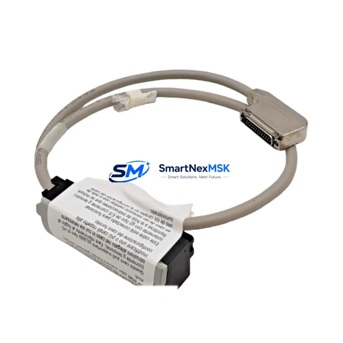
Allen-Bradley 1492-ACABLE010TB Retrofit-Ready Cable for 1492 Series Control Systems
The Allen-Bradley 1492-ACABLE010TB is a 1.0-metre analog pre-wired cable assembly with TB (terminal block) termination, engineered specifically for the 1492 Series wiring system. Designed as a direct drop-in replacement for aging or discontinued cable assemblies in legacy ControlLogix and CompactLogix installations, this component eliminates field-wiring errors, reduces commissioning time, and ensures signal integrity across analog I/O channels during system modernisation projects.
For engineers managing brownfield upgrades, the 1492-ACABLE010TB is a critical interface component. It bridges the analog I/O module — such as the 1756-IF8 eight-channel analog input module or the 1769-IF4 CompactLogix analog input module — to the terminal block wiring infrastructure, preserving existing field wiring while the control platform is upgraded. This approach significantly reduces retrofit risk and keeps downtime within planned maintenance windows.
Upgrade Compatibility Table
| Parameter | Detail |
|---|---|
| SKU / Part Number | 1492-ACABLE010TB |
| Cable Length | 1.0 m (100 cm) |
| Termination Type | TB (Terminal Block) |
| Compatible I/O Modules | 1756-IF8, 1756-OF8, 1769-IF4, 1769-IF4I, 1769-OF4 |
| Compatible Series | Allen-Bradley 1492 Series Wiring System |
| Control Platform | ControlLogix (1756), CompactLogix (1769) |
| Installation Type | DIN-rail mounted terminal block interface |
| Communication Compatibility | Analog signal (4–20 mA / 0–10 V); no protocol conversion required |
| Replacement Scope | Direct drop-in for discontinued or damaged 1492-ACABLE010TB units |
| Commissioning Notes | Verify channel address mapping in RSLogix 5000 / Studio 5000 after swap |
| Warranty | 12 months from date of dispatch |
Retrofit Planning for Existing Automation Systems
When planning a retrofit around the 1492-ACABLE010TB, the scope typically extends well beyond the cable itself. A complete analog I/O retrofit in a ControlLogix or CompactLogix system requires a coordinated review of the entire signal chain and backplane architecture.
Start with the 1756-A7 or 1756-A13 chassis (ControlLogix rack) to confirm available slot positions for replacement I/O modules. If the existing rack is at capacity, a 1756-TBCH or 1756-TBS6H terminal base may need to be added to accommodate additional wiring infrastructure. For CompactLogix systems, the 1769-ECR end cap and bus configuration must be verified before inserting any new 1769-series I/O modules.
Power supply capacity is a frequent oversight in retrofit projects. Confirm that the 1756-PA75 or 1756-PB75 power supply can support the additional current draw of replacement I/O modules. Undersized power supplies are a leading cause of intermittent faults after module swaps. Similarly, for CompactLogix systems, the 1769-PA4 or 1769-PB4 power supply ratings must be cross-checked against the expanded I/O load.
Terminal wiring compatibility is equally critical. The 1492-ACABLE010TB connects to the 1492-AIFM8-F-5 analog interface module or equivalent AIFM-series breakout, which must be present and correctly addressed on the DIN rail. If the existing AIFM module is a legacy variant, verify that the connector pinout matches the replacement cable’s TB termination before energising the circuit.
For systems migrating from older SLC 500 or PLC-5 platforms to ControlLogix, the analog signal scaling parameters stored in the original program must be re-mapped in Studio 5000. The 1747-L553 SLC 5/05 processor or 1785-L80E PLC-5/80E program logic will require conversion using Rockwell’s migration tools, and each analog channel’s engineering unit scaling (EGU) must be validated against the new module’s input range settings.
HMI screen updates are often required in parallel. If the site runs a PanelView Plus 7 (2711P series) or an older PanelView 1000 (2711-T10C8), analog tag addresses linked to the replaced I/O modules must be remapped in FactoryTalk View Studio to reflect the new module slot assignments. Failure to update HMI tag bindings is a common source of post-retrofit alarm nuisance and operator confusion.
Communication link integrity should be verified throughout the retrofit. If the system uses EtherNet/IP via a 1756-EN2T or 1756-EN3TR communication module, confirm that the I/O tree in the controller’s I/O configuration reflects the updated module types and slot positions. For DeviceNet-connected field devices, a 1756-DNB DeviceNet bridge module scan list update may also be required.
Finally, pre-shipment testing of the 1492-ACABLE010TB is conducted at our facility prior to dispatch. Each unit is inspected for continuity, connector seating, and cable jacket integrity. Stock is maintained for immediate dispatch, supporting both planned maintenance schedules and emergency breakdown scenarios.
Downtime Control During System Migration
Minimising unplanned downtime is the primary concern for any brownfield retrofit involving analog I/O cabling. The 1492-ACABLE010TB’s plug-and-play design — with pre-terminated TB connectors on both ends — eliminates field crimping and reduces the risk of wiring errors that typically extend commissioning time.
The recommended approach is a channel-by-channel swap rather than a full I/O module replacement in a single maintenance window. By replacing one 1492-ACABLE010TB at a time and verifying the analog signal reading in Studio 5000 or RSLogix 5000 before proceeding to the next channel, engineers can maintain partial system operation and avoid a full process shutdown. This is particularly valuable in continuous-process environments where a complete control system outage is not operationally acceptable.
Before any cable swap, export and archive the current controller program from the 1756-L73 or 1756-L85E ControlLogix processor (or the relevant CompactLogix 1769-L33ER or 1769-L36ERM controller). This ensures that the original program logic, force tables, and I/O configuration can be restored immediately if the retrofit encounters an unexpected compatibility issue.
Where possible, use the controller’s Program Mode to inhibit the affected I/O module during the cable swap, rather than powering down the entire rack. This preserves the program execution state on unaffected modules and allows the system to resume normal operation within seconds of the replacement cable being seated and the module re-enabled. Post-swap, verify analog input values against known reference signals (e.g., a calibrated 4–20 mA loop calibrator) before returning the channel to automatic control.
Retrofit Support FAQ
Q1: Is the 1492-ACABLE010TB a direct replacement for all 1492-ACABLE010 variants?
The 1492-ACABLE010TB specifically uses TB (terminal block) termination. If your existing installation uses a different termination suffix (e.g., -F for flying leads or -H for high-density connectors), verify the termination type before ordering. The cable length (1.0 m) and analog signal compatibility are consistent across the 1492-ACABLE010 family, but the connector type must match the AIFM module installed on your DIN rail.
Q2: What commissioning steps are required after installing the replacement cable?
After seating the 1492-ACABLE010TB, go online with the controller in Studio 5000 or RSLogix 5000 and navigate to the affected analog I/O module’s properties. Confirm that the module status shows “Running” and that analog input values are within the expected engineering unit range. Apply a known reference signal (e.g., 4 mA = 0%, 20 mA = 100%) to each channel and verify the scaled value in the controller tag database. Document the as-found and as-left readings for your maintenance records.
Q3: Can this cable be used in a migration from SLC 500 to CompactLogix?
Yes. The 1492-ACABLE010TB is compatible with the 1769-series analog I/O modules used in CompactLogix systems. During an SLC 500 to CompactLogix migration, the cable interfaces the new 1769-IF4 or 1769-OF4 module to the existing field wiring via the 1492-AIFM breakout, preserving the terminal block wiring infrastructure and avoiding the need to re-terminate field cables.
Q4: What does the 12-month warranty cover?
All units dispatched by SMARTNEXMSK carry a 12-month warranty covering manufacturing defects, connector integrity, and cable continuity. Units that fail within the warranty period due to verified manufacturing defects will be replaced or refunded. The warranty does not cover damage resulting from incorrect installation, over-voltage conditions, or mechanical abuse. Pre-shipment testing documentation is available upon request.
© 2026 SMARTNEXMSK. All rights reserved.
Original Source: https://smartnexmsk.com
Contact: sales@smartnexmsk.com | +86 18259474341


