Allen-Bradley 1492-AIFM16-F-3 Retrofit-Ready Analog Interface Module for IFM Series Control Systems
The Allen-Bradley 1492-AIFM16-F-3 is a 16-channel analog input interface module (IFM) engineered for seamless integration with Rockwell Automation’s 1756 ControlLogix and 1769 CompactLogix control platforms. As legacy analog I/O wiring systems age out of production support cycles, the 1492-AIFM16-F-3 has become a critical retrofit component for facilities managing aging control cabinets, upgrading discontinued analog terminal blocks, or migrating from older 1771 PLC-5 and SLC 500 architectures to modern Logix-based platforms.
This module provides a structured, pre-wired interface between field-side analog instrumentation and the backplane I/O of Allen-Bradley analog input modules such as the 1756-IF16 and 1756-IF8. By eliminating point-to-point field wiring directly to the I/O module, the 1492-AIFM16-F-3 dramatically reduces installation time, minimizes wiring errors, and simplifies future maintenance — all critical factors when controlling downtime during a live system retrofit.
Upgrade Compatibility Table
| Parameter | Details |
|---|---|
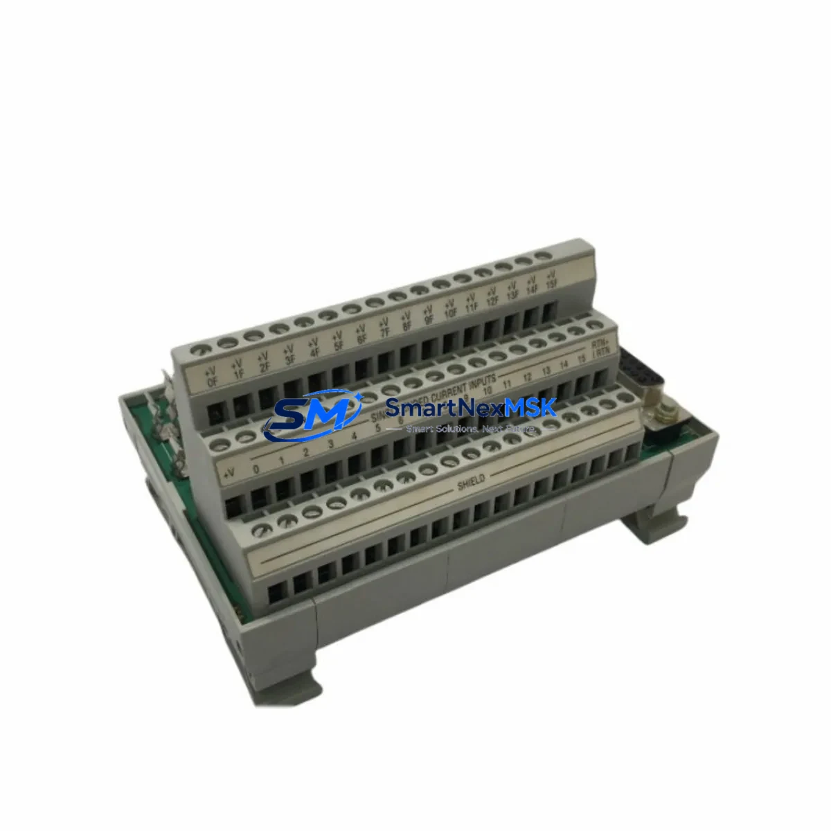
| SKU / Part Number | 1492-AIFM16-F-3 |
| Compatible I/O Modules | 1756-IF16, 1756-IF8, 1769-IF16C, 1769-IF8 |
| Compatible Platforms | ControlLogix (1756), CompactLogix (1769) |
| Channel Count | 16 Analog Input Channels |
| Signal Type | 4–20 mA / 0–10 VDC (field configurable) |
| Terminal Style | Spring-clamp screw terminals (F-type) |
| Mounting | DIN rail, 35 mm standard |
| Backplane Interface | Pre-wired ribbon cable to 1756/1769 analog I/O module |
| Replaces / Upgrades | 1492-AIFM16-F-3 legacy units, 1771-series analog terminal panels |
| Communication Compatibility | EtherNet/IP via parent ControlLogix chassis; no direct module-level protocol |
| Commissioning Notes | Verify ribbon cable orientation; confirm channel-to-tag mapping in Studio 5000 |
| Warranty | 12 Months — covers manufacturing defects and functional failure under normal operating conditions |
Retrofit Planning for Existing Automation Systems
When planning a retrofit around the 1492-AIFM16-F-3, the scope of work typically extends well beyond swapping a single module. A complete analog I/O retrofit in a ControlLogix environment requires a coordinated review of the entire signal chain — from field instruments through terminal blocks, IFM wiring, I/O module configuration, and ultimately the controller tag database in Studio 5000 Logix Designer.
In most legacy installations, the 1492-AIFM16-F-3 is paired with a 1756-IF16 analog input module seated in a 1756-A7 or 1756-A13 ControlLogix chassis. The chassis is powered by a 1756-PA75 or 1756-PB75 power supply, and the controller — typically a 1756-L71 or 1756-L73 — manages the I/O tree via the local backplane. Before removing any existing IFM wiring, engineers should document all field terminal assignments, verify the ribbon cable pinout against the 1492-AIFM16-F-3 wiring diagram, and confirm that the replacement module’s terminal numbering matches the existing field cable labels.
For facilities migrating from older SLC 500 or PLC-5 platforms, the retrofit path often involves installing a new ControlLogix chassis alongside the legacy rack, running parallel I/O for a validation period, and then cutting over. During this phase, a 1756-ENBT or 1756-EN2T EtherNet/IP communication module is typically added to the new chassis to maintain network visibility from the SCADA or DCS layer. If the existing HMI — such as a PanelView Plus 7 — was originally configured for DH+ or DF1 serial communication, a protocol migration to EtherNet/IP must be planned in parallel, including updates to all HMI screen tag bindings.
I/O expansion during the same retrofit window is common. Engineers frequently add 1769-IQ16 discrete input modules or 1769-OF4 analog output modules to CompactLogix expansion racks to accommodate new instrumentation added as part of the modernization project. Each new module requires address assignment in the I/O tree and corresponding tag creation in the controller program — tasks that should be completed and tested in an offline Studio 5000 project before the live cutover.
Programming cable access is also a practical consideration. A 1756-USB or standard USB-to-serial programming cable connected to the controller’s USB port allows on-site engineers to upload the existing program, make tag modifications, and download the updated project without disrupting the running process — provided the controller supports online edits for the affected routines.
Downtime Control During System Migration
Minimizing unplanned downtime is the primary operational constraint in any live control system retrofit. For the 1492-AIFM16-F-3 replacement, the recommended approach is a staged swap: install the new IFM module on a temporary DIN rail section adjacent to the existing unit, transfer field wiring channel by channel while the system remains in manual mode, and verify each analog signal at the I/O module level before switching back to automatic control.
Before beginning any physical work, upload and archive the current controller program from the 1756-L7x or 1756-L8x processor. Store a verified backup on both the local engineering workstation and an off-site location. If the controller supports a Secure Digital (SD) card — as most modern ControlLogix processors do — write a program backup to the card as an additional recovery layer.
During the wiring transfer, use a calibrated loop calibrator to inject a known 4 mA and 20 mA signal at each field terminal and confirm the corresponding tag value in Studio 5000 before moving to the next channel. This channel-by-channel verification approach catches wiring transpositions before they propagate into the running process and eliminates the need for a full system shutdown to diagnose post-cutover signal errors.
Once all 16 channels are verified, the ribbon cable from the 1492-AIFM16-F-3 can be connected to the 1756-IF16 module, the I/O module re-enabled in the I/O tree, and the controller returned to Run mode. Total planned downtime for a single IFM swap using this method is typically under 90 minutes for an experienced controls engineer.
All units supplied by SMARTNEXMSK are pre-tested prior to shipment. Each 1492-AIFM16-F-3 undergoes functional verification of terminal continuity, ribbon cable integrity, and channel isolation before dispatch, reducing the risk of DOA failures on the day of installation.
Retrofit Support FAQ
Q1: Is the 1492-AIFM16-F-3 a direct drop-in replacement for older 1492-series IFM modules?
In most cases, yes. The 1492-AIFM16-F-3 uses the same DIN rail footprint and ribbon cable interface as earlier 1492-AIFM16 variants. However, you should verify the terminal style (screw vs. spring-clamp) and confirm the ribbon cable part number matches your existing 1756-IF16 or 1769-IF16C analog input module before ordering. If you are replacing a unit from a different sub-series, contact our technical team with your existing module label for confirmation.
Q2: What commissioning steps are required after installing the replacement module?
After physical installation, connect the ribbon cable to the analog input module and power up the chassis. In Studio 5000 Logix Designer, go online with the controller and verify that all 16 analog input tags are reading correctly. Use a loop calibrator to inject 4 mA and 20 mA at each terminal and confirm the corresponding tag values fall within ±0.1% of expected. Check that no I/O faults are present in the controller fault log before returning the system to automatic mode.
Q3: Can this module be used with both 4–20 mA and 0–10 VDC field signals?
Yes. The 1492-AIFM16-F-3 supports both current (4–20 mA) and voltage (0–10 VDC) analog input signals. Signal type selection is determined by the configuration of the paired 1756-IF16 or 1769-IF16C analog input module in Studio 5000, not by any physical jumper on the IFM itself. Ensure the I/O module channel configuration matches the field instrument output type before enabling the channel.
Q4: What does the 12-month warranty cover, and what is the return process?
The 12-month warranty covers manufacturing defects and functional failure under normal operating conditions, including terminal block integrity, ribbon cable continuity, and channel isolation. It does not cover damage caused by incorrect wiring, overvoltage, or physical mishandling. To initiate a warranty claim, contact sales@smartnexmsk.com with your order number, a description of the fault, and photos of the installation. Replacement units are dispatched within 3 business days of fault confirmation.
© 2026 SMARTNEXMSK. All rights reserved.
Original Source: https://smartnexmsk.com
Contact: sales@smartnexmsk.com | +86 18259474341


