Allen-Bradley 150-C25NBR Retrofit-Ready Soft Starter for SMC-3 Control Systems
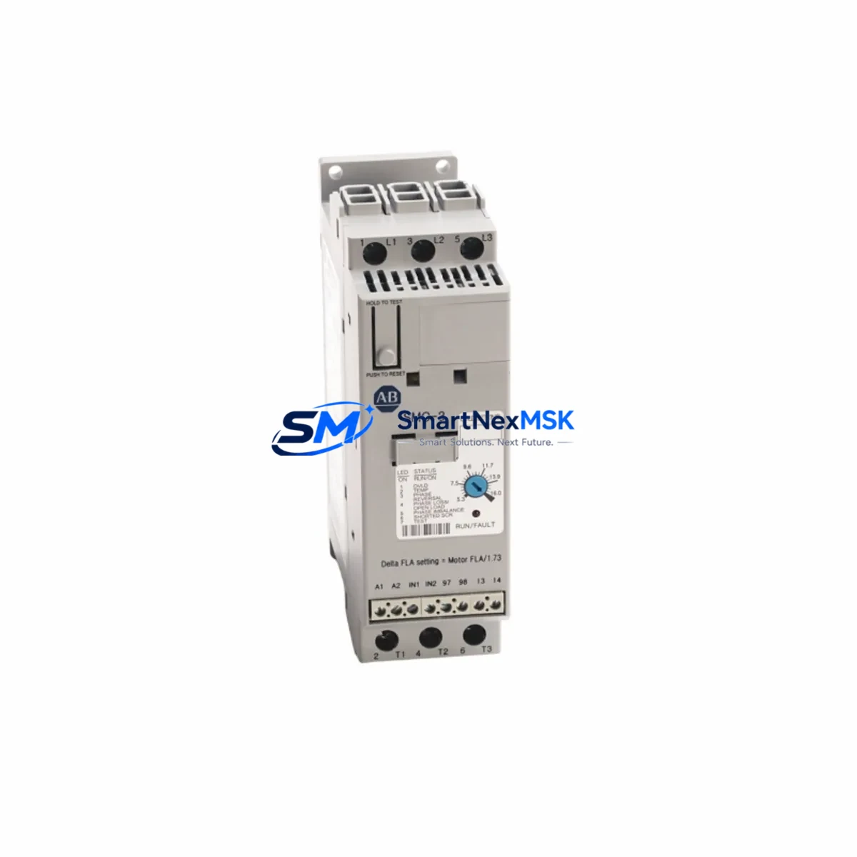
The Allen-Bradley 150-C25NBR is a 25A, 200–480V AC soft starter from the SMC-3 series, engineered for smooth motor starting and stopping in industrial control systems. As a retrofit-ready replacement unit, the 150-C25NBR is a direct substitute for aging or discontinued SMC-3 soft starters installed in legacy motor control centers (MCCs), control cabinets, and standalone drive panels. SMARTNEXMSK maintains verified stock of the 150-C25NBR with full functional testing, original packaging where available, and a 12-month warranty on every unit shipped.
Whether you are upgrading a 1990s-era MCC, replacing a failed unit on a critical production line, or migrating from an older Allen-Bradley SMC Dialog Plus or SMC-2 platform, the 150-C25NBR provides a proven, cost-effective path to system continuity without requiring a full drive replacement or PLC reprogramming cycle.
Upgrade Compatibility Table
| Parameter | Details |
|---|---|
| Model / SKU | Allen-Bradley 150-C25NBR |
| Series | SMC-3 |
| Rated Current | 25A |
| Supply Voltage | 200–480V AC, 3-Phase |
| Control Voltage | 100–240V AC |
| Enclosure / Form Factor | Open Type (Panel Mount) |
| Communication | DeviceNet (via 150-SM2 or 150-SM3 module); standalone operation supported |
| Replaces / Compatible With | 150-C25NBD, 150-C25NRD, SMC Dialog Plus 150-A25NB, SMC-2 equivalent ratings |
| Installation Requirement | DIN rail or panel mount; verify terminal block pitch and bypass contactor wiring |
| Retrofit Recommendation | Confirm bypass contactor (e.g. 100-C30 or 100-C37) rating matches motor FLA |
| Debugging Focus | Parameter 01 (Current Limit), Parameter 03 (Ramp Time), DeviceNet node address |
| Warranty | 12 Months — covers functional failure under normal operating conditions |
Retrofit Planning for Existing Automation Systems
Replacing a 150-C25NBR in an existing control system requires a structured approach to avoid unplanned downtime and protect the integrity of the surrounding automation architecture. Before removing the failed or obsolete unit, engineers should document the existing terminal wiring layout — particularly the L1/L2/L3 line-side connections, T1/T2/T3 load-side connections, and the 3-wire control circuit tied to the 1746-OB16 or similar Allen-Bradley digital output module driving the start/stop logic.
In systems where the SMC-3 is networked via DeviceNet, the 150-SM2 DeviceNet communication module must be transferred to the replacement unit or replaced with a new 150-SM3 module if the existing module shows wear. The DeviceNet node address stored in the module must match the original address configured in the RSNetWorx for DeviceNet project file to avoid scanner faults on the 1756-DNB or 1747-SDN DeviceNet scanner card. If the control system uses a ControlLogix 1756-L71 or CompactLogix 1769-L33ER as the host controller, verify that the Add-On Instruction (AOI) or explicit messaging block referencing the soft starter’s node address is intact before re-energizing the network.
For systems using a legacy SLC 500 platform with a 1747-SDN scanner, the replacement 150-C25NBR must be re-commissioned using DriveExplorer or the SMC-3 handheld programmer (150-HIM-A1) to restore motor nameplate parameters including full-load amps, ramp time, and kickstart settings. In MCC configurations where the soft starter shares a backplane or wireway with a 1606-XLP power supply, a 1492-IFM terminal block interface module, and a 1783-US5T Stratix unmanaged switch for local HMI connectivity, the replacement sequence should follow a defined isolation procedure: de-energize the MCC section, lock out the upstream 140M motor protection circuit breaker, and verify zero-energy state before disconnecting the 150-C25NBR.
Where the original installation used a 22-HIM-C2S remote HMI pod connected to a PowerFlex 40 or PowerFlex 525 in an adjacent cabinet, confirm that the HMI screen parameters referencing motor status from the soft starter are updated to reflect the new unit’s parameter map. In hybrid systems combining soft starters with variable frequency drives, the 150-C25NBR is typically used on fixed-speed loads such as pumps, fans, and compressors, while the PowerFlex 525 handles variable-speed applications — ensure the control logic in Studio 5000 Logix Designer correctly differentiates between the two device types during the retrofit.
For I/O expansion needs during the retrofit, the 1769-IQ16 digital input module and 1769-OB16 digital output module are commonly added to the CompactLogix rack to accommodate additional interlocks, status feedback from the 150-C25NBR auxiliary contacts, and fault relay outputs. If the retrofit involves migrating from a SLC 500 to a CompactLogix platform simultaneously, the 1747-AIC Advanced Interface Converter and 1761-CBL-PM02 programming cable may be needed to extract the original SLC program before conversion using the RSLogix 500 to Studio 5000 migration utility.
Downtime Control During System Migration
Minimizing production downtime during a 150-C25NBR replacement is achievable with proper pre-staging and a disciplined commissioning sequence. SMARTNEXMSK recommends the following approach for critical-path installations:
Pre-Staging: Configure the replacement 150-C25NBR on the bench before the maintenance window. Use the 150-HIM-A1 handheld programmer or DriveExplorer software to pre-load all motor parameters — current limit, ramp time, kickstart voltage, and tachometer feedback settings if applicable. If the unit will operate on DeviceNet, pre-assign the node address using the rotary switches on the 150-SM2 or 150-SM3 module before installation.
Program Protection: Back up the host PLC program (ControlLogix, CompactLogix, or SLC 500) to a secure location using RSLogix 5000 or RSLogix 500 before beginning any wiring work. Verify that the program backup includes all force tables, I/O configuration, and DeviceNet scanner mapping. This ensures that if a fault occurs during commissioning, the original control logic can be restored without delay.
Parallel Verification: Where the process allows, perform a dry-run test with the motor uncoupled from the load to verify ramp-up behavior, current limiting, and fault relay operation before returning the system to production. Confirm that the HMI status display — whether a PanelView 800, PanelView Plus 7, or third-party SCADA screen — correctly reflects the soft starter’s run, fault, and ready states via the DeviceNet or hardwired status signals.
Cutover: Execute the final cutover during a planned low-production window. With the replacement unit pre-staged and verified, the physical swap, terminal reconnection, and network re-commissioning can typically be completed within 30–60 minutes for a standard MCC installation, significantly reducing exposure to unplanned production loss.
Retrofit Support FAQ
Q1: Is the 150-C25NBR a direct drop-in replacement for the 150-C25NBD?
Yes. The 150-C25NBR and 150-C25NBD share the same 25A current rating, terminal layout, and SMC-3 form factor. The primary difference is the control voltage input range. Verify your control circuit voltage (100–240V AC for the NBR variant) matches the existing wiring before installation. No PLC program changes are required for a like-for-like swap.
Q2: Can the 150-C25NBR operate on a DeviceNet network without reconfiguration?
If the replacement unit is pre-configured with the same DeviceNet node address as the original (via the 150-SM2 or 150-SM3 module), the DeviceNet scanner — whether a 1756-DNB or 1747-SDN — will recognize it automatically on power-up. No changes to the RSNetWorx project file or PLC program are required, provided the EDS file version is compatible.
Q3: What wiring checks are required before energizing the replacement unit?
Verify L1/L2/L3 line-side torque values (typically 4–6 Nm for this frame size), confirm T1/T2/T3 load-side connections match the original motor terminal designations, and check that the bypass contactor coil circuit is correctly wired to the soft starter’s bypass output terminals. Inspect the 3-wire control circuit for correct Start, Stop, and Enable signal routing. Use a calibrated clamp meter to confirm motor FLA does not exceed the 25A rating of the 150-C25NBR under loaded conditions.
Q4: What does the 12-month warranty cover, and how is a claim processed?
SMARTNEXMSK’s 12-month warranty covers functional failure of the 150-C25NBR under normal operating conditions, including internal component failure, communication module defects, and parameter memory corruption. Physical damage caused by incorrect wiring, overvoltage events, or environmental contamination is excluded. To initiate a warranty claim, contact sales@smartnexmsk.com with the order number, unit serial number, and a description of the fault. Replacement units are dispatched within 3–5 business days upon claim approval.
© 2026 SMARTNEXMSK. All rights reserved.
Original Source: https://smartnexmsk.com
Contact: sales@smartnexmsk.com | +86 18259474341