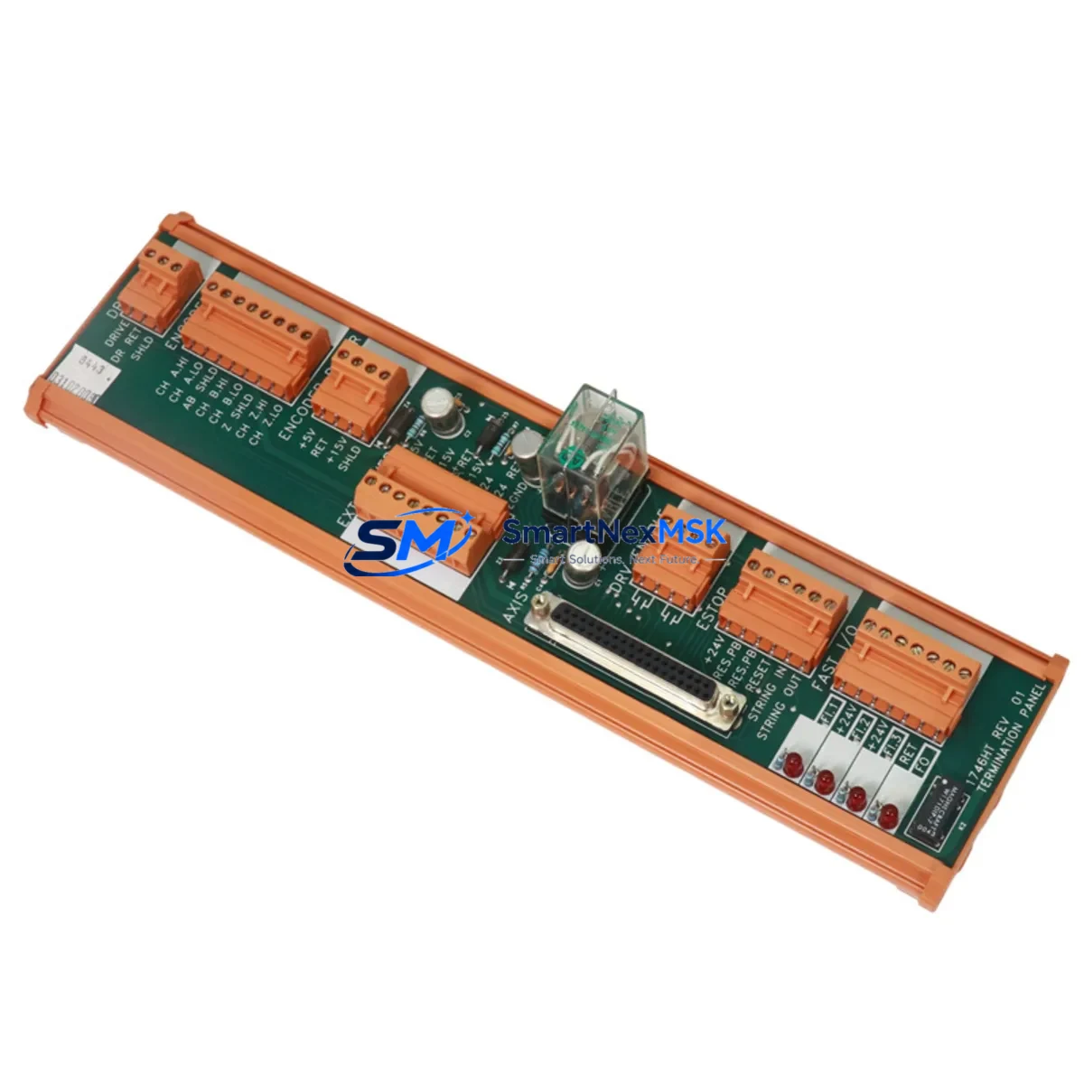
Allen-Bradley 1746-HT Retrofit-Ready I/O Termination Panel for SLC 500 Control Systems
The Allen-Bradley 1746-HT is a field-wiring termination panel engineered for seamless integration into SLC 500 modular control systems. As legacy SLC 500 installations reach end-of-life and original Rockwell Automation spare parts become increasingly scarce, the 1746-HT remains one of the most sought-after retrofit components for engineers tasked with keeping aging production lines operational without a full platform migration. SMARTNEXMSK maintains verified in-stock inventory of the 1746-HT, fully tested and backed by a 12-month warranty, ready for immediate dispatch to minimize unplanned downtime.
Upgrade Compatibility Table
| Parameter | Details |
|---|---|
| Compatible Platform | Allen-Bradley SLC 500 Modular Chassis (1746 series) |
| Compatible Chassis | 1746-A4, 1746-A7, 1746-A10, 1746-A13 |
| Slot Interface | Standard SLC 500 backplane connector — no adapter required |
| Wiring Compatibility | Direct drop-in; existing field wiring terminals retained |
| Communication Protocol | SLC 500 backplane I/O bus (DH-485 compatible environment) |
| Replacement For | Discontinued 1746-HT units; also compatible with 1746-OW16 and 1746-IB16 wiring configurations |
| Installation Requirement | Power-down chassis before installation; verify slot addressing in RSLogix 500 |
| Commissioning Note | Confirm I/O module address in processor file; re-verify HMI tag mapping post-swap |
| Warranty | 12 months from date of shipment — covers manufacturing defects and functional failure |
Retrofit Planning for Existing Automation Systems
Replacing the 1746-HT in an active SLC 500 control cabinet requires a structured approach to avoid cascading failures across interconnected subsystems. Before pulling the existing termination panel, engineers should document all field wiring terminal assignments and cross-reference them against the original I/O configuration in RSLogix 500. The 1746-HT interfaces directly with discrete I/O modules such as the 1746-IB16 (16-point 24VDC input) and 1746-OW16 (16-point relay output), both of which share the same backplane slot architecture and wiring footprint.
Power supply capacity is a critical pre-check. The 1746-P2 or 1746-P4 power supply modules must be verified to have sufficient current headroom after the new termination panel is installed, particularly if additional I/O modules such as the 1746-NI4 analog input module or 1746-NO4I analog output module are being added as part of a broader I/O expansion. Backplane current draw should be recalculated using Rockwell’s chassis sizing tool before finalizing the retrofit BOM.
For installations where the SLC 500 communicates upstream to a SCADA or DCS via DH-485 or RS-232 DF1, the communication link should be validated post-swap using the 1747-PIC programming cable or a 1747-UIC USB-to-DH-485 adapter. If the site is migrating from SLC 500 to a CompactLogix 5380 or ControlLogix 5580 platform, the 1746-HT can serve as a bridging component during phased migration, allowing field wiring to remain intact while the control logic is converted in Studio 5000 Logix Designer.
HMI screens built on PanelView 550 or PanelView Plus 600 terminals that reference SLC 500 data file addresses must be audited for tag remapping if any slot reassignment occurs during the retrofit. Retaining the original slot numbering wherever possible eliminates the need for HMI screen edits and reduces commissioning time significantly.
Downtime Control During System Migration
Minimizing production downtime during a 1746-HT swap begins with pre-staging. The replacement unit should be bench-tested and verified functional before the maintenance window opens. A full backup of the SLC 500 processor program should be saved to a laptop running RSLogix 500 and stored on a USB drive kept on-site. This ensures that if the processor loses its program during power cycling — a known risk with older 1747-L532 or 1747-L541 processors with degraded battery backup — the program can be reloaded within minutes rather than hours.
During the swap, the chassis should be de-energized at the 1746-P2 power supply input, not just at the field device level. After the 1746-HT is seated and field wiring reconnected, power should be restored incrementally: processor first, then I/O modules, then field devices. This sequence protects against output modules energizing field devices before the processor has completed its I/O scan initialization. Once the system is online, a forced I/O test on each channel confirms wiring integrity before returning the line to production. Total planned downtime for a single-slot 1746-HT replacement, when properly pre-staged, typically falls within a 30–60 minute maintenance window.
Retrofit Support FAQ
Q: Is the 1746-HT a direct drop-in replacement for the original discontinued unit?
A: Yes. The 1746-HT is dimensionally and electrically identical to the original Rockwell Automation specification. It seats into any standard SLC 500 modular chassis slot without mechanical modification and uses the same terminal block wiring layout, eliminating the need to re-terminate field cables.
Q: Does the replacement unit require any program changes in RSLogix 500?
A: No program changes are required if the replacement is installed in the same chassis slot as the original. The SLC 500 processor addresses I/O by slot position, so maintaining the original slot assignment preserves all existing rung logic and HMI tag references without modification.
Q: What commissioning checks should be performed after installation?
A: After power-up, verify the processor status LED shows RUN mode without fault codes. Use RSLogix 500 to perform a forced I/O scan on each channel of the adjacent I/O modules. Confirm DH-485 or DF1 communication links are re-established with upstream SCADA or HMI devices. Check the 1746-P2 power supply load indicator to confirm backplane current draw is within rated limits.
Q: What does the 12-month warranty cover?
A: The 12-month warranty covers all manufacturing defects and functional failures under normal operating conditions from the date of shipment. Each unit shipped by SMARTNEXMSK undergoes pre-shipment functional testing. In the event of a warranty claim, SMARTNEXMSK provides a replacement unit or full refund, with return shipping coordinated by our technical support team.
© 2026 SMARTNEXMSK. All rights reserved.
Original Source: https://smartnexmsk.com
Contact: sales@smartnexmsk.com | +86 18259474341


