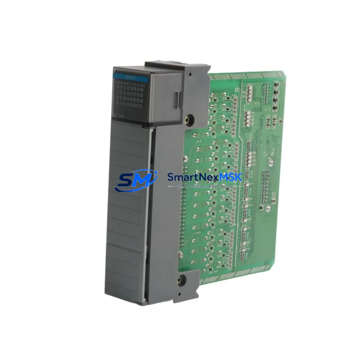
Allen-Bradley 1746-IB32 Retrofit-Ready Input Module for SLC 500 Control Systems
The Allen-Bradley 1746-IB32 is a 32-point 24V DC sink (NPN) digital input module designed for the SLC 500 modular chassis platform. As legacy SLC 500 systems approach end-of-life and original spare parts become increasingly scarce, the 1746-IB32 remains one of the most critical retrofit components for engineers tasked with keeping existing production lines operational without a full PLC migration. SMARTNEXMSK maintains verified stock of the 1746-IB32 with full functional testing, 12-month warranty coverage, and fast global shipping to minimize unplanned downtime.
Whether you are replacing a failed module in a running SLC 5/03 or SLC 5/04 system, upgrading an aging control cabinet, or consolidating spare parts inventory ahead of a planned shutdown, the 1746-IB32 is a direct slot-compatible replacement that requires no program changes, no backplane reconfiguration, and no HMI screen modifications when substituted into the same chassis slot.
Upgrade Compatibility Table
| Parameter | Detail |
|---|---|
| Module SKU | 1746-IB32 |
| Series / Platform | SLC 500 Modular (1746 Series) |
| Input Type | 32-Point 24V DC Sink (NPN) |
| Backplane Interface | SLC 500 1746 Backplane — compatible with 4-slot, 7-slot, 10-slot, and 13-slot chassis (1746-A4, 1746-A7, 1746-A10, 1746-A13) |
| Direct Replacement For | 1746-IB16 (16-point predecessor), 1746-IA16 (AC input variant — requires wiring change), legacy 1746-IB8 in expanded I/O configurations |
| Wiring Compatibility | Two 20-pin removable terminal blocks; field wiring transfers directly from same-generation modules |
| Communication Compatibility | Native SLC 500 backplane protocol; compatible with SLC 5/01, 5/02, 5/03, 5/04, and 5/05 processors |
| Installation Requirement | Power-down chassis before insertion; verify slot address assignment in RSLogix 500 I/O configuration |
| Retrofit Recommendation | Confirm input image table mapping in ladder logic before hot-swap; update I/O tree in RSLogix 500 if slot address changes |
| Commissioning Focus | Verify 24V DC field power supply capacity; test all 32 input points under live field signal before resuming production |
| Warranty | 12-Month Warranty — covers functional failure under normal operating conditions |
Retrofit Planning for Existing Automation Systems
A successful 1746-IB32 retrofit begins well before the module arrives on site. Engineers should start by auditing the existing SLC 500 chassis configuration — identifying the processor model (commonly a 1747-L532 SLC 5/03 or 1747-L541 SLC 5/04), the chassis size, and the current slot assignments for all installed modules. In a typical control cabinet, the 1746-IB32 shares the backplane with components such as the 1746-OB32 32-point DC source output module, the 1746-NO4I analog output module, and the 1746-NI4 analog input module. Each of these modules draws power from the chassis power supply — commonly a 1746-P4 or 1746-P7 — so verifying available backplane current capacity is a mandatory pre-retrofit step.
Terminal block wiring is one of the most time-sensitive tasks during a retrofit. The 1746-IB32 uses two 20-pin removable terminal blocks, which allows field wiring to be pre-terminated on a bench and transferred to the new module without disturbing individual wire connections. This approach significantly reduces the risk of miswiring and shortens the commissioning window. Engineers should photograph the existing terminal block layout and cross-reference against the original panel drawings before removal.
For systems that include a 1747-SDN DeviceNet Scanner or a 1747-KE RS-232 communication module, the retrofit plan must also account for network node addressing and communication link continuity. If the SLC 500 system communicates upstream to a ControlLogix or CompactLogix platform via a 1756-DHRIO Data Highway Plus bridge, the DH+ node address of the SLC processor must remain unchanged throughout the module swap to avoid losing the supervisory SCADA or HMI connection. HMI screens built on PanelView terminals referencing SLC 500 data file addresses — particularly the input image file (I:e.w) — will continue to function correctly as long as the 1746-IB32 is installed in the same chassis slot as the original module.
For sites planning a broader I/O expansion alongside the module replacement, the 1746-IB32 can be paired with a 1746-HSCE2 high-speed counter module or additional 1746-OB16E output modules to extend the control system’s capability without replacing the SLC 5/04 processor. A 1747-UIC USB-to-DH485 programming cable is recommended for on-site RSLogix 500 program verification and online monitoring during commissioning.
Downtime Control During System Migration
Minimizing production downtime during a 1746-IB32 replacement requires a structured pre-outage preparation protocol. Before the scheduled maintenance window, the site engineer should upload and archive the current SLC 500 program from the processor using RSLogix 500, storing a timestamped backup on both a local workstation and a removable drive kept in the control cabinet. This ensures that if any unexpected program corruption occurs during the module swap, the original ladder logic can be restored within minutes.
During the outage, the recommended sequence is: de-energize the field devices connected to the input module, remove the terminal blocks from the existing 1746-IB32 (or its predecessor), seat the replacement module firmly into the chassis slot until the locking tab engages, reattach the terminal blocks, and restore power to the chassis. The SLC processor will perform an automatic I/O configuration check on power-up. If the replacement module is installed in the same slot with the same module type, the processor will resume normal scan without requiring a program download.
For sites where even a brief interruption is unacceptable, a parallel chassis strategy can be employed: a second SLC 500 chassis pre-loaded with a tested 1746-IB32 and all associated modules is prepared offline, wired to a terminal strip, and validated against the live program before the cutover. This approach reduces the active switchover time to under 15 minutes and preserves the original control logic, HMI tag bindings, and communication link configurations without modification.
All 1746-IB32 units shipped by SMARTNEXMSK undergo point-by-point functional testing prior to dispatch. Each module is verified for correct input response across all 32 channels, backplane communication integrity, and LED indicator operation. A test report is available upon request. The 12-month warranty covers any functional failure arising under normal operating conditions from the date of shipment.
Retrofit Support FAQ
Q1: Is the 1746-IB32 a direct drop-in replacement for the 1746-IB16?
The 1746-IB32 is electrically and mechanically compatible with the SLC 500 backplane and occupies the same single-slot footprint as the 1746-IB16. However, because the 1746-IB32 provides 32 input points versus 16, the I/O configuration in RSLogix 500 must be updated to reflect the expanded input image table. Field wiring for the original 16 inputs transfers directly; the additional 16 input terminals can be wired to new field devices or left unterminated.
Q2: What wiring changes are required when replacing a 1746-IA16 AC input module with the 1746-IB32?
The 1746-IA16 is an AC input module (120V AC), while the 1746-IB32 is a 24V DC sink input module. A direct substitution requires rewiring all field devices from 120V AC to 24V DC signal sources. The terminal block pinout differs between AC and DC modules, so the existing terminal block cannot be transferred without modification. Confirm field device voltage compatibility and update the panel wiring drawings before proceeding.
Q3: How is the 1746-IB32 commissioned after installation?
After seating the module and restoring chassis power, connect to the SLC processor using a 1747-UIC USB-to-DH485 programming cable and open the project in RSLogix 500. Verify the I/O configuration tree reflects the 1746-IB32 in the correct slot. Go online with the processor and monitor the input image file (I:e.w) in real time while activating each field input device to confirm all 32 channels respond correctly. Document the commissioning results and retain the test record with the panel maintenance log.
Q4: What does the 12-month warranty cover, and how is a warranty claim processed?
The 12-month warranty covers functional failure of the 1746-IB32 under normal operating conditions — including backplane communication faults, input channel failures, and LED indicator malfunctions — from the date of shipment. It does not cover damage resulting from incorrect installation voltage, physical impact, or operation outside the module’s rated environmental specifications. To initiate a warranty claim, contact SMARTNEXMSK at sales@smartnexmsk.com with the order reference number and a description of the fault. A replacement unit or full refund will be arranged within the warranty period.
© 2026 SMARTNEXMSK. All rights reserved.
Original Source: https://smartnexmsk.com
Contact: sales@smartnexmsk.com | +86 18259474341


