Allen-Bradley 1746-NI16I Maintenance-Ready Spare SLC 500: Spare Replacement & Industrial Downtime Risk Control
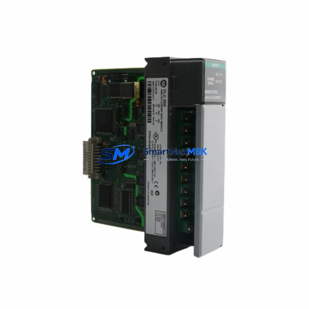
The Allen-Bradley 1746-NI16I is a 16-channel analog input module designed for the SLC 500 modular chassis platform. As a critical signal acquisition component in process control, machine automation, and discrete manufacturing environments, this module handles voltage and current analog signals from field sensors including thermocouples, RTDs, pressure transmitters, and flow meters. When this module fails or degrades, the entire control loop it serves goes blind — making a verified, ready-to-ship spare an essential element of any serious maintenance strategy.
Sourced as an original Allen-Bradley unit, the 1746-NI16I spare stocked through SMARTNEXMSK undergoes pre-shipment functional verification and is backed by a 12-month warranty. Whether you are managing a planned shutdown, responding to an unscheduled fault, or building out your critical spare inventory, this module ships promptly with full documentation support.
Spare Maintenance Table
| Parameter | Specification |
|---|---|
| Part Number | 1746-NI16I |
| Brand | Allen-Bradley (Rockwell Automation) |
| Series | SLC 500 |
| Module Type | 16-Channel Analog Input |
| Input Signal Types | Current (4–20 mA), Voltage (0–10 V, ±10 V) |
| Resolution | 12-bit (plus sign) |
| Backplane Current Draw | 250 mA @ 5 VDC |
| Operating Temperature | 0°C to 60°C (32°F to 140°F) |
| Chassis Compatibility | 1746-A4, 1746-A7, 1746-A10, 1746-A13 |
| Processor Compatibility | SLC 5/01, 5/02, 5/03, 5/04, 5/05 |
| Installation | Slot-based, hot-swap not supported — power down before replacement |
| Origin | USA |
| Condition | Original, pre-shipment tested |
| Warranty | 12 Months |
| Application Environment | Industrial control panels, process automation, discrete manufacturing |
| Maintenance Recommendation | Inspect wiring terminations, verify channel calibration, check backplane seating annually |
Maintenance Planning for Continuous Operation
When a 1746-NI16I analog input module is flagged for replacement during a scheduled inspection or emergency fault response, experienced maintenance engineers know that the module itself is rarely the only component requiring attention. A thorough site assessment should accompany every analog module swap to prevent repeat failures and ensure the restored control loop performs reliably.
Begin by inspecting the 1746-P4 or 1746-P7 power supply module supplying the chassis. Degraded output voltage — even within nominal tolerance — can cause intermittent analog read errors that mimic module failure. Verify backplane voltage stability before condemning the 1746-NI16I. Next, examine the 1746-A7 or 1746-A10 chassis backplane for corrosion, bent connector pins, or thermal stress marks, particularly in high-humidity or high-vibration environments.
Field wiring connected to the 1746-NI16I’s screw terminals should be inspected for insulation breakdown, loose terminations, and shield grounding continuity. In multi-loop installations, the 1746-NO4I analog output module operating in the same chassis should be cross-checked — analog output drift often correlates with input module degradation caused by shared power rail noise. If the system uses thermocouple or RTD inputs routed through the 1746-NI16I, verify that signal isolators or signal conditioners upstream of the module are functioning correctly, as ground loops and common-mode voltage are leading causes of premature analog module failure.
For SLC 500 systems with communication requirements, inspect the 1747-SDN DeviceNet Scanner or 1747-KE RS-232 Interface Module if the analog data is being transmitted upstream to a supervisory system. Communication module faults can mask analog input errors in diagnostic logs. In control cabinets where the 1746-NI16I is installed alongside 1746-OB16 or 1746-IB16 digital I/O modules, check for cross-talk or shared terminal block wiring issues that may have contributed to the analog module’s degradation.
Fuse holders and terminal blocks (such as Allen-Bradley 1492-series)** serving the analog input field circuits should be inspected for oxidation and proper torque. In older SLC 500 installations approaching end-of-life, it is also advisable to assess the condition of the 1747-L553 or 1747-L543 SLC 5/05 or 5/04 processor module — processor firmware and battery status directly affect analog data integrity and scan cycle reliability. Proactively stocking a processor spare alongside the 1746-NI16I reduces total downtime risk in aging systems.
Site Replacement Workflow
Step 1 — Pre-replacement documentation: Before powering down, record all channel configurations, scaling parameters, and alarm setpoints from RSLogix 500 or RSLogix Micro. Export the current program to a backup file. Note the slot position of the 1746-NI16I in the chassis.
Step 2 — Safe power-down: The SLC 500 platform does not support hot-swap for analog modules. Initiate a controlled shutdown via the processor’s RUN/PROG switch, then de-energize the 1746-P4/P7 power supply. Verify zero voltage at the chassis backplane before proceeding.
Step 3 — Module extraction and inspection: Remove the 1746-NI16I by releasing the top and bottom locking tabs. Inspect the backplane connector on both the module and chassis for damage. Photograph the field wiring terminal layout before disconnecting.
Step 4 — Spare installation: Insert the replacement 1746-NI16I into the same slot. Reconnect field wiring per the documented terminal layout. Ensure all screw terminals are torqued to specification (typically 0.8–1.1 Nm for 1746-series terminal blocks).
Step 5 — Power-up and verification: Restore power and place the processor in RUN mode. Use RSLogix 500 to verify all 16 channels are reading within expected engineering unit ranges. Compare live values against known-good historical trends to confirm calibration integrity. Log the replacement date, module serial number, and technician ID in the maintenance record.
This workflow minimizes total downtime to under 60 minutes for a prepared maintenance team and ensures the restored system meets original design specifications without requiring re-commissioning of the broader control loop.
Spare Parts Support FAQ
Q1: Is the 1746-NI16I still available as a new original unit, or only as refurbished stock?
SMARTNEXMSK supplies original Allen-Bradley 1746-NI16I modules sourced through authorized industrial distribution channels. Each unit is pre-shipment tested and ships with a 12-month warranty. Refurbished units are clearly identified separately. If you require factory-new certification documentation, contact our sales team prior to ordering.
Q2: How do I confirm compatibility with my existing SLC 500 chassis and processor before ordering?
The 1746-NI16I is compatible with all SLC 500 modular chassis (1746-A4 through 1746-A13) and all SLC 5/01 through 5/05 processors. Compatibility is determined by chassis slot availability and processor I/O addressing capacity, not firmware version. Provide your chassis catalog number and processor series when contacting us for pre-order compatibility confirmation.
Q3: What is included in the pre-shipment testing process?
Each 1746-NI16I undergoes functional verification including backplane communication check, channel input response test across the full 4–20 mA and voltage input range, and visual inspection for physical damage. A test report is available upon request. Units that do not pass all test criteria are not shipped.
Q4: What is the recommended spare inventory strategy for SLC 500 analog input modules in a critical production environment?
For facilities operating SLC 500 systems in continuous or semi-continuous production, the standard recommendation is to maintain a minimum of one 1746-NI16I spare per chassis that contains analog input modules, with an additional buffer unit for facilities with three or more SLC 500 chassis. Given the age profile of most SLC 500 installations and Rockwell Automation’s end-of-life status for this platform, long-term supply availability cannot be guaranteed — early procurement of multi-year spare stock is strongly advised.
© 2026 SMARTNEXMSK. All rights reserved.
Original Source: https://smartnexmsk.com
Contact: sales@smartnexmsk.com | +86 18259474341


