Allen-Bradley 1746-NI4 Retrofit-Ready Analog Input for SLC 500 Control Systems
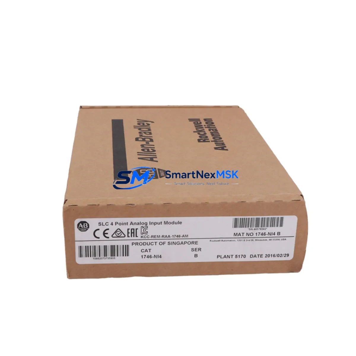
The Allen-Bradley 1746-NI4 is a 4-channel analog input module designed for the SLC 500 modular chassis platform. As legacy SLC 500 systems continue to operate across manufacturing, water treatment, and process control facilities worldwide, the 1746-NI4 remains one of the most frequently requested retrofit and replacement components in the field. Whether you are restoring a failed module, upgrading an aging control cabinet, or migrating signal wiring from a discontinued predecessor, the 1746-NI4 provides a direct, wiring-compatible solution that minimizes engineering rework and keeps your line running.
Each unit accepts voltage and current signals across configurable input ranges, including 0–10 VDC, ±10 VDC, 0–20 mA, and 4–20 mA, making it compatible with the vast majority of field transmitters already installed in your process. The module occupies a single slot in any standard 1746 series rack — including the 1746-A4, 1746-A7, 1746-A10, and 1746-A13 chassis — and communicates natively over the SLC 500 backplane without requiring additional configuration hardware or protocol converters.
Upgrade Compatibility Table
| Parameter | Detail |
|---|---|
| SKU / Part Number | 1746-NI4 |
| Brand / Manufacturer | Allen-Bradley (Rockwell Automation) |
| Compatible Series | SLC 500 (SLC 5/01, 5/02, 5/03, 5/04, 5/05) |
| Compatible Chassis | 1746-A4, 1746-A7, 1746-A10, 1746-A13 |
| Analog Input Channels | 4 channels (differential) |
| Input Signal Types | Voltage: 0–10 V, ±10 V; Current: 0–20 mA, 4–20 mA |
| Resolution | 12-bit (1 in 4,096) |
| Backplane Interface | SLC 500 native backplane — no gateway required |
| Slot Requirement | Single slot, any I/O slot position |
| Power Consumption | Supplied by 1746 backplane; verify chassis power budget before installation |
| Terminal Wiring | Removable screw-terminal block; field wiring retained during module swap |
| Common Replaced Models | 1746-NI4 (earlier revisions), 1746-NIO4I, 1746-NIO4V (partial overlap) |
| Programming Software | RSLogix 500 / Studio 5000 Logix Designer (offline SLC mode) |
| Communication Protocol | SLC 500 backplane (DH-485 / DH+ via processor) |
| Commissioning Tool | 1747-UIC USB-to-DH-485 adapter or 1747-PIC serial cable |
| Warranty | 12 months from date of shipment |
| Condition | New / Surplus New / Tested Refurbished (specify at order) |
Retrofit Planning for Existing Automation Systems
Replacing a failed or end-of-life 1746-NI4 in a live production environment requires careful pre-work to avoid extended downtime. Begin by documenting the existing module address — the slot number within the chassis — because RSLogix 500 ladder logic references analog data using file N-type or F-type integer files mapped directly to that slot position. If the replacement module is installed in the same slot, no program changes are required; the processor will resume scanning the same file addresses immediately after a warm restart.
Before removing the old module, verify the chassis power budget. The 1746-P2 or 1746-P4 power supply feeding the rack must have sufficient current headroom on the 5 VDC and 24 VDC rails to support the replacement module. This is especially important in fully populated racks where a 1746-A13 chassis may already be running near its rated capacity with a mix of digital I/O modules such as the 1746-IB16 and 1746-OB16, plus other analog modules.
The removable terminal block on the 1746-NI4 allows field wiring to remain connected during the module swap. Label each wire before removal as a precaution, then transfer the terminal block directly to the new module. This eliminates re-termination errors and significantly reduces commissioning time. For 4–20 mA loop-powered transmitters, confirm that the loop supply — often sourced from a 1746-NI4 internal 24 VDC rail or an external loop power supply — is correctly re-established after the swap.
If your retrofit also involves migrating from an older SLC 5/03 processor to a SLC 5/05 with Ethernet/IP capability, the 1746-NI4 remains fully compatible. The processor upgrade does not affect analog module addressing or wiring. However, if you are transitioning to a CompactLogix L3x or ControlLogix L7x platform, the 1746-NI4 cannot be used directly — you would instead require a 1769-IF4 CompactLogix analog input module or a 1756-IF16 ControlLogix analog input card, and a full I/O remapping exercise in Studio 5000 would be necessary.
For systems that include an HMI — such as a PanelView 600 or PanelView Plus 700 communicating over DH-485 — the analog tag addresses displayed on screen are derived from the same RSLogix 500 data files. Provided the module slot address is unchanged, HMI screens will continue to display correct engineering-unit values without modification. If the slot address changes for any reason, update the corresponding data file references in both RSLogix 500 and the PanelView application before going live.
Downtime Control During System Migration
Minimizing unplanned downtime during a 1746-NI4 replacement starts with preparation before the maintenance window opens. Upload and archive the current processor program using RSLogix 500 or the 1747-UIC programming cable before touching any hardware. Store the .RSS backup file in at least two locations. This protects your ladder logic, data file configurations, and I/O module definitions against accidental loss during the swap.
During the replacement, place the SLC 500 processor in Program mode rather than performing a hard power-down where possible. This suspends output scanning while preserving the program in RAM, allowing a faster return to Run mode once the new module is seated and the terminal block is reconnected. After seating the 1746-NI4, perform a controlled transition back to Run mode and monitor the analog input data file in RSLogix 500 online mode to confirm that all four channels are returning expected engineering-unit values before releasing control back to the process.
For critical processes where even a brief interruption is unacceptable, consider pre-staging the replacement module on a bench test rack — such as a spare 1746-A4 chassis with a 1746-P1 power supply — and verifying channel calibration and signal integrity before the scheduled maintenance window. This approach reduces in-field commissioning time to under 15 minutes in most cases and allows the maintenance team to confirm module health without process risk.
All 1746-NI4 units supplied by SMARTNEXMSK are function-tested prior to shipment. Each module undergoes channel-by-channel signal verification across the full input range, and a test report is available upon request. Combined with our 12-month warranty, this ensures that the replacement module performs to specification from the moment it is installed.
Retrofit Support FAQ
Q1: Is the 1746-NI4 a direct drop-in replacement for earlier revisions of the same part number?
Yes. All hardware revisions of the 1746-NI4 share the same form factor, terminal block pinout, and backplane interface. The replacement module can be installed in the same slot without any program changes in RSLogix 500, provided the slot address remains identical.
Q2: What wiring changes are required when replacing the 1746-NI4?
None, in most cases. The removable screw-terminal block retains all field wiring. Simply unplug the terminal block from the old module, seat the new module in the chassis, and reattach the terminal block. Verify loop power continuity for 4–20 mA circuits before returning to Run mode.
Q3: How do I verify the replacement module is functioning correctly after installation?
Connect to the SLC 500 processor using RSLogix 500 and the 1747-UIC adapter. Go online, navigate to the analog input data file associated with the module’s slot, and confirm that all four channels display live, plausible engineering-unit values. Cross-reference against known field transmitter readings to validate calibration accuracy.
Q4: What does the 12-month warranty cover, and what is the return process?
The 12-month warranty covers manufacturing defects and functional failures under normal operating conditions. If a module fails within the warranty period, contact SMARTNEXMSK with your order reference and a description of the fault. We will arrange a replacement or repair at no additional cost. All units are function-tested before shipment to minimize field failures.
© 2026 SMARTNEXMSK. All rights reserved.
Original Source: https://smartnexmsk.com
Contact: sales@smartnexmsk.com | +86 18259474341


