Allen-Bradley 1746-NI8 Retrofit-Ready Analog Input for SLC 500 Control Systems
The Allen-Bradley 1746-NI8 is an 8-channel analog input module designed for the SLC 500 modular I/O platform. As legacy SLC 500 systems approach end-of-life and original 1746-NI8 units become increasingly difficult to source through standard distribution channels, this module serves as a verified retrofit-ready replacement for facilities managing aging control infrastructure. Whether you are upgrading a control cabinet, recovering from an unplanned module failure, or executing a planned migration away from discontinued hardware, the 1746-NI8 provides a direct, rack-compatible solution that preserves your existing wiring, program logic, and HMI screen configurations without requiring a full system redesign.
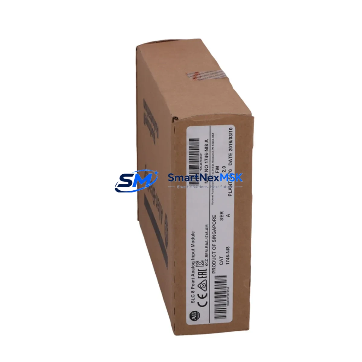
Each unit is tested prior to shipment against Allen-Bradley SLC 500 backplane communication standards. The module occupies a single slot in any 1746-A4, 1746-A7, 1746-A10, or 1746-A13 chassis and is addressed through the standard SLC 500 I/O addressing scheme, meaning your existing RSLogix 500 ladder logic files require no modification to accommodate the replacement module. Input channel configuration — including current/voltage range selection via jumper settings — matches the original factory specification, allowing field technicians to complete the swap and return the system to production with minimal downtime.
Upgrade Compatibility Table
| Parameter | Detail |
|---|---|
| Compatible Chassis | 1746-A4, 1746-A7, 1746-A10, 1746-A13 |
| Slot Requirement | 1 slot (any I/O slot position) |
| Input Channels | 8 single-ended analog inputs |
| Input Range | ±10 VDC, 0–5 VDC, 0–10 VDC, 4–20 mA (jumper selectable per channel) |
| Resolution | 12-bit (0–4095 counts) |
| Backplane Communication | SLC 500 parallel backplane (DH-485 compatible system) |
| Wiring Terminal | Removable screw-terminal block (compatible with original 1746-NI8 wiring) |
| Program Compatibility | RSLogix 500 — no logic modification required |
| HMI Compatibility | PanelView 300, 550, 600, 900, 1000 (existing tag addresses retained) |
| Replacement For | 1746-NI8 (all revisions), 1746-NI4 (with channel reduction) |
| Retrofit Recommendation | Direct drop-in replacement; verify jumper settings before power-on |
| Commissioning Note | Confirm module address in RSLogix 500 I/O configuration after installation |
| Warranty | 12 months from date of shipment |
Retrofit Planning for Existing Automation Systems
Successful integration of the 1746-NI8 into an existing SLC 500 control system begins well before the module arrives on site. Retrofit planning should account for the full scope of the control cabinet: the 1746-P2 or 1746-P4 power supply must be verified to have sufficient current capacity to support the analog input module alongside existing digital I/O cards such as the 1746-IB16 and 1746-OB16. If the cabinet is running near its power budget, a power supply upgrade or load redistribution across chassis slots may be required before the new module is installed.
Terminal wiring from field instruments — typically 4–20 mA transmitters for pressure, temperature, flow, or level — connects to the removable screw-terminal block on the 1746-NI8. Because the terminal block is removable, the original wiring harness from the failed module can be transferred directly to the replacement unit, eliminating the need to re-terminate individual conductors. Technicians should photograph the original wiring layout and confirm signal polarity before disconnecting the old module.
In systems where the SLC 500 communicates upstream to a supervisory SCADA platform via a 1747-KE or 1747-SDN communication module, the analog data collected by the 1746-NI8 is passed through the backplane to the SLC 5/04 or SLC 5/05 processor and then forwarded over DH+ or DeviceNet to the host system. No changes to the communication module configuration are required when replacing a like-for-like analog input card. However, if the retrofit is part of a broader migration from SLC 500 to a ControlLogix or CompactLogix platform, the 1756-IF8 or 1769-IF8 analog input modules in the target platform will require new tag mapping and updated HMI faceplates on any connected PanelView Plus terminals.
For facilities managing multiple SLC 500 racks across a production line, it is advisable to maintain at least one spare 1746-NI8 per rack configuration. Unplanned analog input failures in process control applications — particularly those monitoring critical loop variables — can trigger process shutdowns that far exceed the cost of a spare module. Pairing the 1746-NI8 with a documented spare-parts register that also covers the 1746-OW16 relay output module, the 1746-BTM barrel temperature module, and the 1747-L543 SLC 5/04 processor ensures that the most failure-prone components in the system are covered by on-hand inventory.
Downtime Control During System Migration
Minimizing production downtime during an analog input module replacement requires a structured approach that protects the integrity of the existing control program and maintains field control continuity throughout the swap procedure. The recommended sequence begins with a full backup of the SLC 500 processor program using RSLogix 500 or RSLinx Classic, saved to a secure offline location before any hardware is disturbed. This backup preserves all rung logic, data file values, and I/O configuration parameters, providing a recovery baseline if the replacement procedure encounters unexpected complications.
Once the backup is confirmed, the affected process loop should be placed in manual mode at the operator workstation — typically a PanelView 550 or PanelView 900 HMI — so that field actuators hold their last commanded position while the module is swapped. The SLC 500 processor should be placed in Program mode via the key switch on the 1747-L543 or equivalent processor before the chassis power is removed. After the 1746-NI8 is seated in the correct slot and the terminal block is reconnected, power is restored and the processor is returned to Run mode. The I/O status indicators on the new module should illuminate within seconds of power-on, confirming backplane communication is established.
Final commissioning involves verifying live analog input values in RSLogix 500 data monitor against known field instrument readings. Each of the eight channels should be checked individually, with particular attention to channels that feed PID control loops. Once all channels are confirmed accurate, the process loops can be returned to automatic mode and normal production resumed. Total elapsed downtime for a prepared technician performing a like-for-like 1746-NI8 replacement is typically 30 to 90 minutes, depending on cabinet accessibility and the number of active process loops requiring manual handoff.
Retrofit Support FAQ
Q: Is the 1746-NI8 a direct replacement for all revisions of the original Allen-Bradley 1746-NI8?
A: Yes. The module is compatible with all hardware revisions of the 1746-NI8 and installs into the same chassis slot without modification. Jumper settings for input range selection should be verified against the original module configuration before installation.
Q: Will my existing RSLogix 500 program need to be modified after the replacement?
A: No program modification is required for a like-for-like replacement. The I/O address mapping, data file references, and rung logic remain valid. If the module is being installed in a different slot position than the original, the I/O configuration in RSLogix 500 must be updated to reflect the new slot address before downloading to the processor.
Q: What pre-shipment testing is performed on each unit?
A: Each 1746-NI8 is functionally tested on a live SLC 500 backplane prior to shipment. Testing covers backplane communication, all eight analog input channels across the full input range, and LED status indicator operation. A test report is available upon request.
Q: What does the 12-month warranty cover?
A: The 12-month warranty covers defects in materials and workmanship under normal operating conditions. It includes free replacement or repair of the module if a verified failure occurs within the warranty period. The warranty does not cover damage resulting from incorrect installation, overvoltage conditions, or physical mishandling. Contact our technical team at sales@smartnexmsk.com to initiate a warranty claim.
© 2026 SMARTNEXMSK. All rights reserved.
Original Source: https://smartnexmsk.com
Contact: sales@smartnexmsk.com | +86 18259474341


