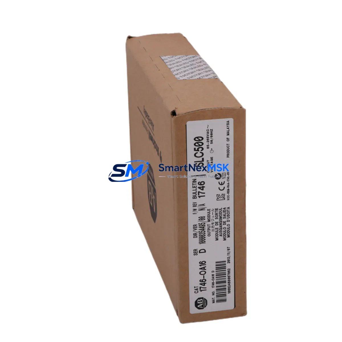
Allen-Bradley 1746-OA16 Maintenance-Ready Spare SLC 500
The Allen-Bradley 1746-OA16 is a 16-point AC output module designed for the SLC 500 modular chassis platform. Rated at 120/240VAC per output point, this module serves as a critical field-replaceable unit in discrete control panels across manufacturing, utilities, material handling, and process automation environments. When an output module fails, the entire I/O rack segment goes dark — conveyors stop, actuators freeze, and production halts. Stocking a verified original 1746-OA16 spare eliminates the guesswork and dramatically compresses mean-time-to-repair (MTTR).
Each unit shipped by SMARTNEXMSK undergoes pre-shipment functional verification, including output channel continuity checks, backplane connector inspection, and visual examination for capacitor aging or relay contact wear. All units carry a 12-month warranty covering manufacturing defects and functional failure under normal operating conditions. Fast dispatch is standard — most orders ship within 1–2 business days from confirmed payment.
Spare Maintenance Table
| Parameter | Specification |
|---|---|
| Part Number / SKU | 1746-OA16 |
| Series / Platform | SLC 500 Modular I/O |
| Module Type | AC Discrete Output |
| Output Points | 16 (sourcing, TRIAC) |
| Output Voltage Range | 85–265VAC, 47–63Hz |
| Output Current per Point | 0.5A continuous (max 8A surge) |
| Backplane Compatibility | 1746-A4, 1746-A7, 1746-A10, 1746-A13 |
| Isolation | Optical isolation, field side to backplane |
| Indicators | 16 output status LEDs |
| Operating Temperature | 0°C to 60°C (32°F to 140°F) |
| Relative Humidity | 5–95% non-condensing |
| Installation | Slide-in modular slot, no tools required |
| Certifications | UL, CSA, CE |
| Condition | Original, pre-shipment tested |
| Warranty | 12 Months |
Maintenance Planning for Continuous Operation
When a 1746-OA16 output module is flagged during a control cabinet inspection or fault log review, experienced maintenance engineers know that the module itself is rarely the only component requiring attention. A systematic replacement workflow should include inspection of the following associated components to prevent repeat failures and ensure full system restoration.
Begin with the 1746-P2 or 1746-P4 power supply — an aging or undersized power supply is a leading cause of premature output module failure due to voltage sag under load. Verify output voltage stability under full I/O load before reinstalling a new module. Next, inspect the 1746-A7 or 1746-A10 chassis backplane for bent connector pins, corrosion, or cracked PCB traces at the slot where the failed module was seated.
On the field wiring side, check the terminal block wiring and screw torque on the 1746-OA16’s output connector. Loose terminals cause intermittent output faults that are often misdiagnosed as module failure. If the outputs drive inductive loads such as solenoid valves or motor starters, verify that surge suppressors or snubber circuits are installed across each load — missing suppression is a common cause of TRIAC degradation.
For panels where the SLC 500 communicates upstream to a SCADA or DCS, inspect the 1747-SDN DeviceNet Scanner or 1747-KE DH-485 communication module for firmware version compatibility and cable integrity. A communication module fault can mask output module status in the HMI, leading to delayed fault diagnosis.
If the system includes analog I/O in the same chassis, cross-check the 1746-NI4 or 1746-NO4I analog modules for signal drift — power supply instability that damages a digital output module can simultaneously degrade analog reference voltages. For facilities running mixed SLC 500 and MicroLogix architectures, also review the 1762-OW16 relay output module as a potential cross-platform spare for lower-voltage output circuits.
Finally, confirm that the 1747-L543 or 1747-L553 SLC 5/04 or 5/05 processor firmware is current and that the I/O configuration table in RSLogix 500 matches the physical slot assignment after module replacement. A slot mismatch will cause the processor to fault on first scan after power-up.
Site Replacement Workflow
Step 1 — Isolate and document: Place the SLC 500 processor in Program mode via the keyswitch or RSLogix 500 before removing the 1746-OA16. Record the slot number, wiring labels, and any active output force conditions in the fault log.
Step 2 — Remove and inspect: Disconnect the field wiring connector from the module face. Slide the module out of the chassis slot. Inspect the backplane connector on the removed module and the chassis slot for damage before inserting the replacement unit.
Step 3 — Install replacement: Slide the new 1746-OA16 into the same slot. Reconnect the field wiring connector, verifying terminal torque to specification (typically 0.8–1.1 Nm). The module is hot-swappable in most SLC 500 configurations, but cold insertion is recommended for first-time replacements to avoid transient backplane faults.
Step 4 — Verify and restore: Return the processor to Run mode. Monitor the 16 output status LEDs on the module face and confirm output states match the ladder logic conditions in RSLogix 500. Clear any I/O fault bits in the processor status file (S:1/13) before resuming production.
Step 5 — Update maintenance records: Log the replacement date, module serial number, and any associated findings (power supply voltage readings, wiring condition, chassis slot condition) in the plant CMMS. Schedule a follow-up inspection of the power supply and chassis within 30 days.
Spare Parts Support FAQ
Q1: Is the 1746-OA16 still available as a new original part?
A: Yes. SMARTNEXMSK maintains stock of original Allen-Bradley 1746-OA16 modules sourced through authorized industrial distribution channels. Each unit is individually tested prior to shipment and ships with a 12-month warranty. We recommend maintaining at least one spare per chassis in your critical spare parts inventory to eliminate lead-time risk during unplanned downtime events.
Q2: What is the compatibility scope of the 1746-OA16 across SLC 500 chassis sizes?
A: The 1746-OA16 is compatible with all standard SLC 500 modular chassis — the 4-slot 1746-A4, 7-slot 1746-A7, 10-slot 1746-A10, and 13-slot 1746-A13. It is not compatible with the SLC 500 fixed controllers (1747-L20, 1747-L30, 1747-L40) which use integrated I/O. Always verify the chassis catalog number before ordering.
Q3: How is the module tested before shipment?
A: Each 1746-OA16 unit undergoes a pre-shipment inspection protocol that includes backplane connector pin integrity check, output channel TRIAC continuity verification, LED indicator function test, and visual inspection for physical damage, capacitor condition, and PCB contamination. Units that do not pass all checks are quarantined and not shipped. Test records are retained for warranty traceability.
Q4: What is covered under the 12-month warranty?
A: The 12-month warranty covers functional failure of the module under normal operating conditions consistent with Allen-Bradley published specifications. It covers manufacturing defects, component failure, and backplane interface faults. It does not cover damage resulting from incorrect installation, overvoltage events, physical impact, or operation outside rated environmental conditions. Warranty claims are processed with return authorization and typically resolved within 5–7 business days.
—
© 2026 SMARTNEXMSK. All rights reserved.
Original Source: https://smartnexmsk.com
Contact: sales@smartnexmsk.com | +86 18259474341


