Allen-Bradley 1747-L531 Retrofit-Ready Processor for SLC 500 Control Systems
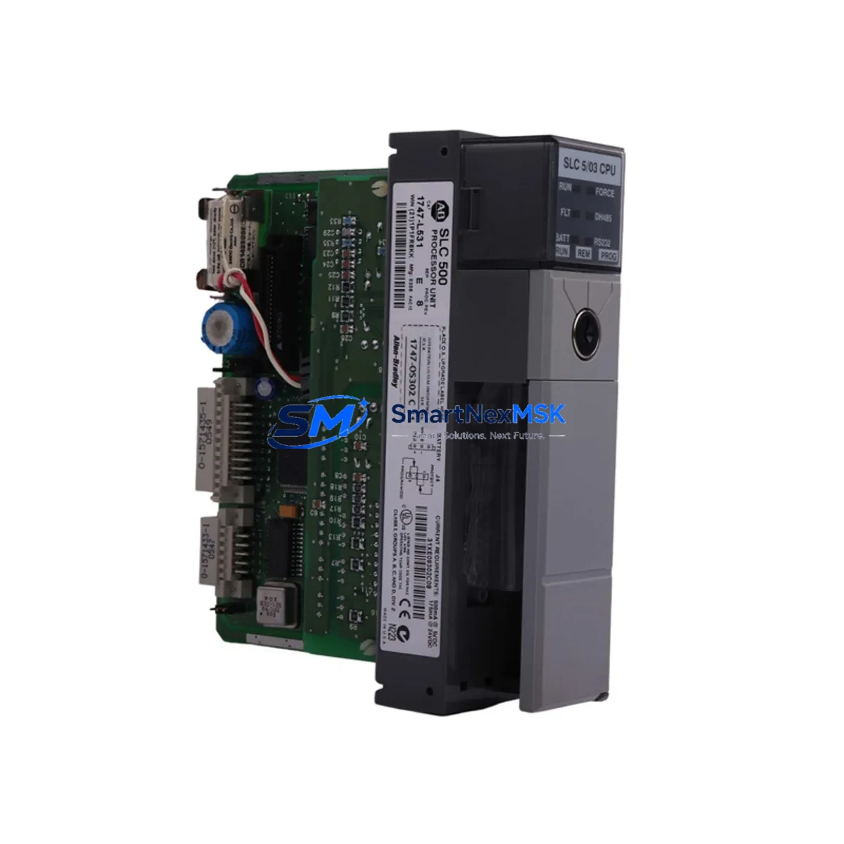
The Allen-Bradley 1747-L531 is a SLC 5/03 processor module with 8K of user memory, designed for installation in the SLC 500 modular chassis. As legacy SLC 500 systems approach end-of-life and original spare parts become increasingly scarce, the 1747-L531 remains one of the most sought-after retrofit and replacement components for facilities that need to extend the operational life of their existing control infrastructure without committing to a full migration to the ControlLogix or CompactLogix platform.
This unit is sourced from verified industrial supply channels, inspected, and function-tested prior to dispatch. Each shipment is covered by a 12-month warranty against manufacturing defects and operational failure under normal industrial use conditions.
Upgrade Compatibility Table
| Parameter | 1747-L531 (SLC 5/03) | Notes for Retrofit |
|---|---|---|
| Chassis Compatibility | SLC 500 Modular Chassis (1746-A4, 1746-A7, 1746-A10, 1746-A13) | Slot 0 installation required; verify chassis backplane revision |
| User Memory | 8K words | Sufficient for most legacy ladder logic programs; verify program size before swap |
| Communication Ports | DH-485 (Port 1), RS-232 (Port 2) | Confirm HMI and SCADA communication protocol matches; DH+ requires 1747-KE bridge |
| Programming Software | RSLogix 500 / Studio 5000 Logix Designer (offline) | Use 1747-UIC or 1747-CP3 programming cable for direct connection |
| Power Supply Requirement | Supplied via 1746-P2 or 1746-P4 chassis power supply | Verify power supply capacity covers all installed I/O modules |
| I/O Addressing | Up to 4096 I/O points (local + remote) | Re-verify I/O map after processor swap; remote I/O via 1747-ASB adapter |
| Replacement for | 1747-L511, 1747-L514, 1747-L524, 1747-L532 | Program re-download required; verify memory size compatibility |
| Warranty | 12-Month Warranty — covers operational failure under normal industrial use | |
Retrofit Planning for Existing Automation Systems
When planning a retrofit around the 1747-L531, the scope of work typically extends well beyond the processor module itself. A complete SLC 500 control cabinet will include a combination of digital and analog I/O modules such as the 1746-IB16 (16-point 24VDC input) and 1746-OB16 (16-point 24VDC output), along with specialty modules like the 1746-NI4 analog input or 1746-NO4I analog output for process control loops. These modules remain in place during a processor swap, but their slot addresses and I/O configuration files must be verified against the replacement processor’s program.
The chassis power supply — typically a 1746-P2 (5A) or 1746-P4 (10A) — must be assessed for total current draw after any I/O expansion. If the retrofit involves adding communication capability, a 1747-SDN DeviceNet scanner or a 1747-AENTR EtherNet/IP adapter may be introduced into the rack, increasing the power budget. Always calculate the chassis load before finalizing the module configuration.
For facilities running PanelView or PanelView Plus HMI terminals communicating over DH-485, the 1747-L531’s built-in DH-485 port (Port 1) provides direct connectivity without additional hardware. However, if the existing HMI communicates over DH+ or EtherNet/IP, a protocol bridge such as the 1761-NET-AIC or a 1747-KE DH-485 to DH+ gateway will be required. Confirm the HMI screen tag database references the correct processor node address before going live.
Remote I/O drops connected via the 1747-ASB Remote I/O Adapter must be re-scanned after the processor replacement. Verify that the remote chassis rack addresses and module group assignments in the program match the physical installation. Any discrepancy will result in I/O faults at startup. For systems using a 1747-SN Remote I/O Scanner, confirm the scanner’s baud rate and last rack settings are preserved in the replacement processor’s program file.
Programming cables are a frequently overlooked retrofit consumable. The 1747-UIC USB-to-DH-485 interface cable or the legacy 1747-CP3 RS-232 cable should be on-hand before the cutover window begins. Having RSLogix 500 installed on a dedicated laptop with the existing program backed up to at least two separate media ensures that program restoration can be completed within the planned maintenance window.
Downtime Control During System Migration
Minimizing unplanned downtime during a processor swap on a live production line requires disciplined pre-work. Before the cutover, upload and verify the existing program from the 1747-L531 (or its predecessor) using RSLogix 500, and save the .RSS file with a timestamped backup. Document all data file values — particularly N, F, T, C, and R files — that hold process setpoints or accumulated values, as these are not retained in the processor’s battery-backed memory if the battery has degraded.
During the swap, the SLC 500 chassis remains powered down only for the duration of the physical module exchange — typically under five minutes for an experienced technician. The replacement 1747-L531 should be pre-loaded with the verified program offline before installation. Upon power-up, force a full I/O scan and confirm that all input and output status indicators on the 1746-IB16 and 1746-OB16 modules reflect the expected field states before releasing the system to automatic mode.
For critical processes where even brief interruptions are unacceptable, consider staging the replacement processor in a parallel test rack with a mirrored I/O configuration before the live cutover. This approach allows full program verification — including communication link tests to the HMI and any upstream SCADA system — without touching the production chassis. Once verified, the cutover becomes a straightforward module swap with a pre-validated program, reducing the risk of extended downtime caused by unexpected compatibility issues.
Retrofit Support FAQ
Q: Is the 1747-L531 a direct drop-in replacement for the 1747-L524 (SLC 5/02)?
A: The 1747-L531 is physically compatible with the same SLC 500 modular chassis and occupies Slot 0 in the same manner as the 1747-L524. However, the SLC 5/03 instruction set is a superset of the SLC 5/02, so programs written for the 5/02 will generally run on the 5/03 without modification. Confirm that the program does not rely on any 5/02-specific behavior and that the memory size (8K on the L531 vs. 4K on the L524) is sufficient for the existing program.
Q: What communication cable is needed to download a program to the 1747-L531?
A: The 1747-L531 supports programming via its RS-232 port (Port 2) using the 1747-CP3 cable, or via its DH-485 port (Port 1) using the 1747-UIC USB-to-DH-485 interface. The 1747-UIC is the recommended option for modern laptops that lack a native RS-232 port. Ensure the RSLogix 500 driver (DF1 for RS-232 or DH-485 for Port 1) is correctly configured in RSLinx Classic before attempting the download.
Q: How is the 1747-L531 tested before shipment?
A: Each unit undergoes a functional power-on test to verify processor initialization, memory integrity, and communication port operation. Units that fail any stage of the test are quarantined and not dispatched. A 12-month warranty covers the replacement or repair of any unit that exhibits operational failure under normal industrial use conditions from the date of receipt.
Q: Can the 1747-L531 communicate with a PanelView 550 HMI over DH-485?
A: Yes. The 1747-L531’s Port 1 is a native DH-485 port and is directly compatible with PanelView 550 terminals configured for DH-485 communication. Ensure the node address assigned to the processor in the HMI’s communication setup matches the DH-485 node address configured in the processor’s channel configuration. No additional hardware or protocol converter is required for this configuration.
© 2026 SMARTNEXMSK. All rights reserved.
Original Source: https://smartnexmsk.com
Contact: sales@smartnexmsk.com | +86 18259474341


