Allen-Bradley 1747-M11/B Maintenance-Ready Spare SLC 500 Automation
The Allen-Bradley 1747-M11/B is a 64K user memory module designed for the SLC 500 programmable controller platform — one of the most widely deployed small-to-mid-range PLC families in discrete manufacturing, material handling, and process control environments. As original equipment reaches end-of-life and Rockwell Automation phases out legacy support, maintaining a verified stock of the 1747-M11/B becomes a critical element of any industrial maintenance strategy. This listing provides a genuine, tested spare module sourced for maintenance engineers and procurement teams who cannot afford unplanned downtime caused by memory module failure or corruption.
Whether you are managing a scheduled turnaround, responding to an unplanned fault, or building a resilience inventory for aging SLC 500 control systems, the 1747-M11/B delivers the exact memory capacity and firmware compatibility required to restore operation without reprogramming or hardware reconfiguration. Each unit is inspected and function-tested prior to shipment, backed by a 12-month warranty, and available for rapid dispatch to minimize production interruption.
Spare Maintenance Table
| Parameter | Specification |
|---|---|
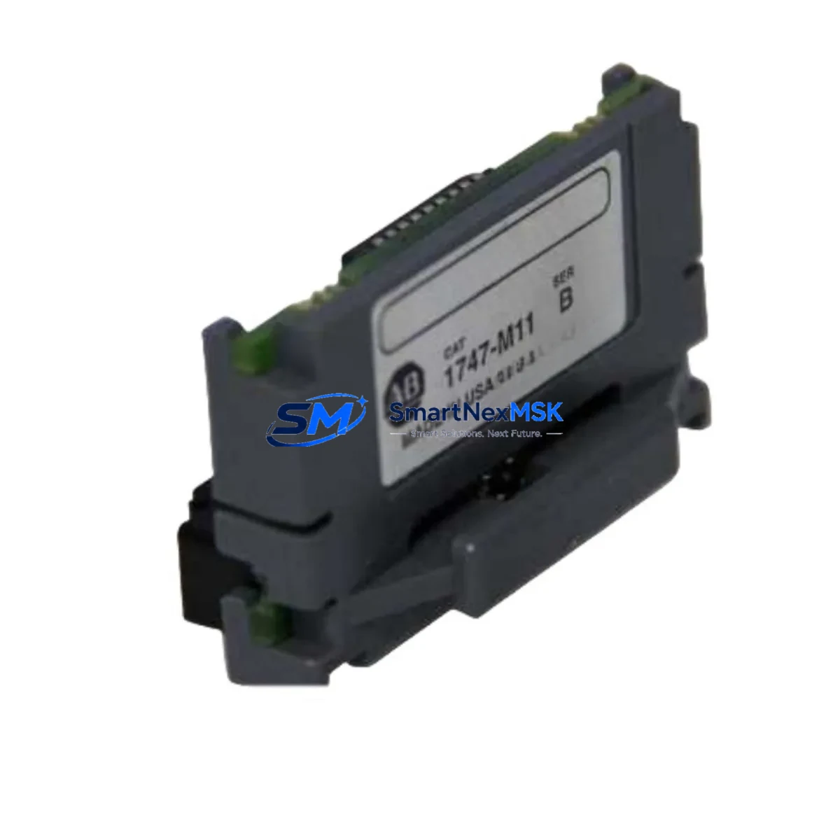
| Part Number / SKU | 1747-M11/B |
| Brand | Allen-Bradley (Rockwell Automation) |
| Series | SLC 500 |
| Module Type | User Memory Module (EEPROM) |
| Memory Capacity | 64K Words |
| Compatible Processors | SLC 5/03 (1747-L532/L533), SLC 5/04 (1747-L541/L542/L543), SLC 5/05 (1747-L551/L552/L553) |
| Installation Method | Direct plug-in to processor module memory socket |
| Operating Temperature | 0°C to 60°C (32°F to 140°F) |
| Storage Temperature | -40°C to 85°C |
| Application Environment | Industrial control panels, MCC enclosures, standalone PLC racks |
| Maintenance Role | Program backup, processor replacement, memory restore after fault |
| Pre-shipment Testing | Function-tested and inspected before dispatch |
| Warranty | 12 Months |
| Origin | United States |
| Condition | Original / Genuine |
Maintenance Planning for Continuous Operation
The 1747-M11/B does not operate in isolation — it is one component within a broader SLC 500 control system that requires coordinated maintenance to ensure long-term reliability. When replacing or inspecting the memory module, maintenance engineers should treat the event as an opportunity to audit the surrounding hardware for wear, degradation, or compatibility risk.
Begin with the processor itself: the 1747-L553 (SLC 5/05 processor) or 1747-L543 (SLC 5/04 processor) should be checked for firmware revision compatibility with the memory module revision /B. Confirm that the processor’s battery — typically a 1747-BA lithium battery — is within its service life, as a depleted battery can cause RAM data loss even when the EEPROM module is present and functional.
Inspect the 1746-P4 or 1746-P7 power supply module for output voltage stability. An under-voltage condition during a write cycle is a known cause of memory module corruption. If the power supply is original equipment from the early 2000s, proactive replacement should be part of the same maintenance window.
Review the I/O rack configuration: 1746-IB16 digital input modules and 1746-OB16 digital output modules should be checked for blown fuses, failed output transistors, and loose field wiring terminations. A field wiring fault that causes repeated processor faults can accelerate memory write cycles and reduce module lifespan.
For systems using analog control loops, inspect 1746-NI4 analog input modules and 1746-NO4I analog output modules for signal drift or calibration deviation. These modules are often overlooked during memory-focused maintenance but are common sources of nuisance faults that trigger unnecessary processor resets.
If the SLC 500 system communicates via DH+ or DH-485, verify the integrity of the 1747-SDN DeviceNet scanner or 1747-KE communication interface module. Communication module faults can cause the processor to enter fault mode, which may trigger a memory reload from the 1747-M11/B — making the module’s integrity critical to network recovery.
Finally, inspect the 1746-A10 or 1746-A13 chassis backplane for corrosion on the card-edge connectors. Oxidized backplane contacts are a leading cause of intermittent processor faults in older SLC 500 installations and can cause the memory module to appear faulty when the root cause is mechanical.
Site Replacement Workflow
Replacing the 1747-M11/B in a live SLC 500 system requires a structured approach to avoid program loss and minimize downtime. Follow this sequence for a safe, efficient replacement:
Step 1 — Backup verification: Before removing the existing module, confirm that a current backup of the ladder logic program exists on an engineering workstation running RSLogix 500 or Studio 5000 Logix Designer (legacy mode). If no backup exists, upload the program from the processor RAM before proceeding.
Step 2 — Controlled shutdown: Place the processor keyswitch in the PROG position to halt execution. Notify operations personnel and confirm that all field outputs are in a safe state before de-energizing the control panel.
Step 3 — Module extraction: With the processor powered down, carefully remove the existing 1747-M11/B from the memory socket on the processor faceplate. Handle by the edges only — avoid contact with the gold connector pins.
Step 4 — New module installation: Insert the replacement 1747-M11/B firmly into the memory socket until fully seated. Verify the module revision (/B) matches the processor’s supported memory revision as listed in the 1747-UM011 user manual.
Step 5 — Program restore and verification: Power up the processor and use RSLogix 500 to download the verified program backup to the processor. After download, switch the keyswitch to RUN and monitor the first scan for any I/O faults or communication errors.
Step 6 — System validation: Confirm all I/O points are responding correctly, analog signals are within expected ranges, and communication links (DH+, DH-485, or Ethernet if applicable) are re-established. Document the replacement in the site maintenance log with the module serial number and date.
This workflow is compatible with both planned maintenance windows and emergency replacement scenarios. The 1747-M11/B’s plug-and-play design means that a trained technician can complete the physical replacement in under 15 minutes, with total system restoration typically achievable within one hour including program verification.
Spare Parts Support FAQ
Q1: Is the 1747-M11/B still available as a new original part, and what is its lifecycle status?
The 1747-M11/B has been discontinued by Rockwell Automation as part of the broader SLC 500 platform end-of-life program. However, genuine original units remain available through authorized industrial spare parts distributors. Each unit we supply is sourced from verified channels, inspected for physical integrity, and function-tested before shipment. We maintain ongoing stock to support customers with long-term SLC 500 installations that are not yet scheduled for migration to newer platforms such as the CompactLogix or ControlLogix families.
Q2: How do I verify compatibility between the 1747-M11/B and my specific SLC 5/04 or SLC 5/05 processor?
Compatibility is determined by the processor catalog number and firmware revision. The 1747-M11/B (64K) is compatible with SLC 5/03 processors at firmware series C or later, SLC 5/04 processors at firmware series C or later, and SLC 5/05 processors at all firmware revisions. Refer to Rockwell Automation publication 1747-UM011 for the complete memory module compatibility matrix. If you provide your processor catalog number and series letter, our technical team can confirm compatibility before shipment.
Q3: What pre-shipment testing is performed, and what does the 12-month warranty cover?
Every 1747-M11/B unit undergoes a physical inspection for connector pin condition, housing integrity, and label legibility, followed by a functional test to verify read/write operation. The 12-month warranty covers defects in materials and workmanship under normal operating conditions. It does not cover damage resulting from incorrect installation, overvoltage events, or use outside the specified environmental ratings. Warranty claims are processed with priority dispatch of a replacement unit to minimize customer downtime.
Q4: Can I use the 1747-M11/B as a program backup medium for disaster recovery, and how should I manage it in my spare parts inventory?
Yes — the 1747-M11/B is specifically designed to serve as a non-volatile program backup. Once a program is stored to the EEPROM module, it will retain the program indefinitely without battery power, making it ideal for disaster recovery kits and cold-spare inventories. Best practice is to store one programmed module per critical processor in a labeled, anti-static bag at ambient temperature, and to refresh the stored program whenever a significant program revision is made. For facilities with multiple SLC 500 processors, we recommend maintaining at least two spare modules per processor family to cover both immediate replacement and backup retention needs.
© 2026 SMARTNEXMSK. All rights reserved.
Original Source: https://smartnexmsk.com
Contact: sales@smartnexmsk.com | +86 18259474341


