Allen-Bradley 1747-SDN Maintenance-Ready Spare SLC 500: Spare Replacement & Industrial Downtime Risk Control
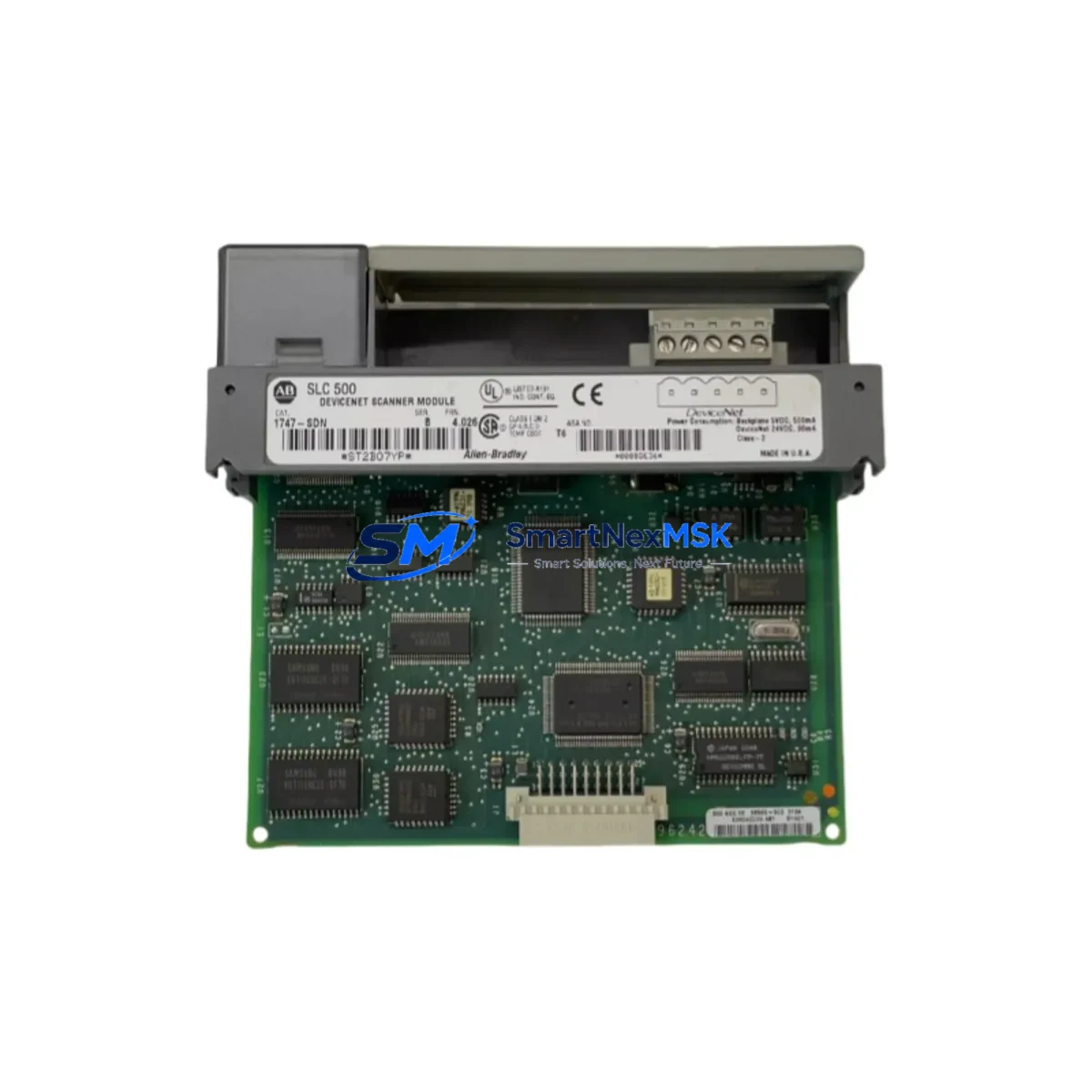
The Allen-Bradley 1747-SDN is a DeviceNet Scanner Module designed for the SLC 500 programmable controller platform. As a single-slot scanner occupying one slot in the SLC 500 chassis, it manages DeviceNet network communications between the SLC 500 processor and field devices including drives, sensors, valve manifolds, and distributed I/O blocks. In industrial environments where DeviceNet networks underpin continuous production lines, conveyor systems, packaging machinery, and process control loops, the 1747-SDN is a critical communication node. A failed or degraded scanner module can halt an entire DeviceNet segment, triggering unplanned downtime that cascades across dependent systems.
Holding a verified, tested 1747-SDN spare on-site is the most direct strategy for minimizing mean time to repair (MTTR) when a DeviceNet communication fault is diagnosed. SMARTNEXMSK supplies original Allen-Bradley 1747-SDN units sourced from authorized channels, each inspected and function-tested prior to shipment, and covered by a 12-month warranty. Our long-term inventory commitment ensures availability even as the SLC 500 platform matures into its extended lifecycle phase.
Spare Maintenance Table
| Parameter | Specification / Detail |
|---|---|
| Part Number / SKU | 1747-SDN |
| Brand | Allen-Bradley (Rockwell Automation) |
| Series | SLC 500 |
| Module Type | DeviceNet Scanner Module |
| Network Protocol | DeviceNet (CAN-based, IEC 62026-3) |
| Chassis Compatibility | SLC 500 fixed and modular chassis (1746 series) |
| Slot Requirement | Single slot, any I/O slot in SLC 500 chassis |
| DeviceNet Node Capacity | Up to 63 nodes per network segment |
| Input Data Table Size | Up to 248 words |
| Output Data Table Size | Up to 248 words |
| Supply Voltage | Backplane powered via SLC 500 chassis |
| Operating Temperature | 0 °C to 60 °C (32 °F to 140 °F) |
| Storage Temperature | -40 °C to 85 °C |
| Relative Humidity | 5% to 95% non-condensing |
| Certifications | UL, CE, CSA (refer to product nameplate) |
| Origin | USA |
| Condition | Original, function-tested before shipment |
| Warranty | 12 Months |
| Typical Application | DeviceNet network master for SLC 500 control systems in manufacturing, material handling, and process automation |
| Maintenance Recommendation | Inspect DeviceNet trunk cable, drop cables, and termination resistors during each planned replacement; verify node addresses before commissioning spare |
Maintenance Planning for Continuous Operation
When a maintenance or procurement engineer schedules replacement of the 1747-SDN, the replacement event should be treated as a broader control cabinet inspection opportunity. The 1747-SDN interfaces directly with the SLC 500 processor — typically a 1747-L532, 1747-L541, or 1747-L553 — through the chassis backplane. Before or during the scanner replacement, engineers should verify that the processor firmware revision is compatible with the replacement module and that the SLC 500 chassis (1746-A4, 1746-A7, 1746-A10, or 1746-A13) shows no signs of backplane connector wear or corrosion.
The DeviceNet network segment served by the 1747-SDN relies on a correctly terminated trunk cable. Both ends of the trunk must carry 121-ohm termination resistors; missing or degraded termination is a common root cause of intermittent communication faults that are misdiagnosed as scanner module failures. Inspect the DeviceNet power supply — often a dedicated 24 VDC DeviceNet power supply unit — for output voltage stability and current headroom, particularly if the node count is near the segment maximum.
Drop cables connecting field devices such as PowerFlex 40 or PowerFlex 400 variable frequency drives, 1734 POINT I/O adapters, 1769 CompactLogix remote I/O, photoelectric sensors, and valve manifold controllers should be inspected for insulation damage, connector seating, and correct node address DIP switch settings. A node address conflict introduced during a prior maintenance event can prevent the replacement 1747-SDN from scanning the network correctly after commissioning.
Inside the control cabinet, review the 24 VDC control power supply feeding the SLC 500 chassis. Verify that the 1746-P1, 1746-P2, or 1746-P4 power supply module is within its rated load capacity and that its output voltage is within tolerance. Fuse holders and circuit breakers protecting the control power rail should be inspected for contact resistance and thermal discoloration. Terminal blocks on the I/O wiring side — particularly those associated with digital output modules such as the 1746-OB16 or 1746-OW16 — should be checked for loose terminations that could cause intermittent field device faults unrelated to the DeviceNet scanner itself.
If the SLC 500 system includes a 1747-KE or 1747-KFC15 communication interface for DH-485 or DF1 serial connectivity to an HMI panel such as a PanelView 550 or PanelView 600, verify that the HMI communication parameters remain intact after the scanner replacement, as some technicians inadvertently alter processor communication settings during module swap procedures. Signal isolators on analog I/O channels — particularly on 1746-NI4 or 1746-NO4I modules — should be checked for drift if the system has been in service for more than five years.
Site Replacement Workflow
Step 1 — Pre-replacement documentation: Export the current RSLogix 500 project file and record the 1747-SDN scanner configuration, including the scanlist, electronic data sheet (EDS) assignments, and I/O mapping table. This ensures the replacement module can be configured identically without relying on memory or undocumented field changes.
Step 2 — Safe de-energization: Follow site lockout/tagout (LOTO) procedures. De-energize the SLC 500 chassis via the control power isolator. Confirm zero energy state on the DeviceNet network power supply before disconnecting the DeviceNet trunk drop cable from the 1747-SDN.
Step 3 — Module removal and inspection: Remove the faulty 1747-SDN from its chassis slot. Inspect the backplane connector pins for damage or contamination. Clean the slot if necessary before inserting the replacement unit.
Step 4 — Replacement installation: Insert the SMARTNEXMSK-supplied 1747-SDN into the same chassis slot. Reconnect the DeviceNet drop cable. Restore control power and verify that the module’s LED indicators show normal status (Module OK solid green, Network OK solid green).
Step 5 — Configuration restore and verification: Using RSNetWorx for DeviceNet, upload the saved scanlist configuration to the replacement module. Verify all nodes are online and communicating. Perform a controlled test cycle before returning the system to production.
This workflow is applicable whether the 1747-SDN is being replaced on an emergency basis following a fault or as part of a planned preventive maintenance cycle. The same procedure supports legacy system life extension programs where aging SLC 500 installations are maintained in service alongside newer ControlLogix or CompactLogix platforms.
Spare Parts Support FAQ
Q1: Is the SMARTNEXMSK 1747-SDN an original Allen-Bradley unit or a compatible replacement?
All 1747-SDN units supplied by SMARTNEXMSK are original Allen-Bradley (Rockwell Automation) modules. We do not supply counterfeit, rebranded, or third-party compatible substitutes. Each unit is sourced from verified supply channels and undergoes functional testing before shipment.
Q2: How do I verify compatibility with my existing SLC 500 chassis and processor revision?
The 1747-SDN is compatible with all SLC 500 modular chassis (1746-A4 through 1746-A13) and all SLC 5/03, 5/04, and 5/05 processors. Compatibility with specific firmware revisions can be confirmed via the Rockwell Automation Product Compatibility and Download Center (PCDC). Our technical team can assist with compatibility verification prior to order confirmation — contact sales@smartnexmsk.com with your processor catalog number and firmware revision.
Q3: What pre-shipment testing is performed on each 1747-SDN unit?
Each unit undergoes power-on functional testing to verify backplane communication, DeviceNet port integrity, and LED status indicator operation. Units that do not pass testing are not shipped. A test report summary is available upon request for critical spare applications.
Q4: What does the 12-month warranty cover, and what is the spare parts lifecycle support commitment?
The 12-month warranty covers defects in materials and workmanship under normal operating conditions. It does not cover damage resulting from incorrect installation, overvoltage events, or physical mishandling. SMARTNEXMSK maintains long-term inventory of SLC 500 platform components to support customers operating legacy systems beyond the standard product lifecycle. Repeat orders and blanket purchase agreements for critical spare programs are supported.
© 2026 SMARTNEXMSK. All rights reserved.
Original Source: https://smartnexmsk.com
Contact: sales@smartnexmsk.com | +86 18259474341


