Allen-Bradley 1756-A10 Retrofit-Ready Chassis for ControlLogix Systems
The Allen-Bradley 1756-A10 is a 10-slot ControlLogix backplane chassis designed for seamless integration into both new installations and legacy system retrofits. As industrial facilities transition away from aging PLC-5, SLC 500, and early ControlLogix platforms, the 1756-A10 serves as the structural backbone for a modernized control architecture — accommodating processor modules, I/O modules, communication adapters, and power supply units within a single unified rack.
Whether you are replacing a failed chassis in an active production line, upgrading a control cabinet from an obsolete 1771 I/O rack, or expanding an existing ControlLogix system to accommodate additional I/O capacity, the 1756-A10 provides the slot density and backplane bandwidth required for demanding industrial applications. Its 10-slot configuration is particularly well-suited for mid-scale automation systems where a balance between module capacity and cabinet footprint is critical.
Upgrade Compatibility Table
| Parameter | Details |
|---|---|
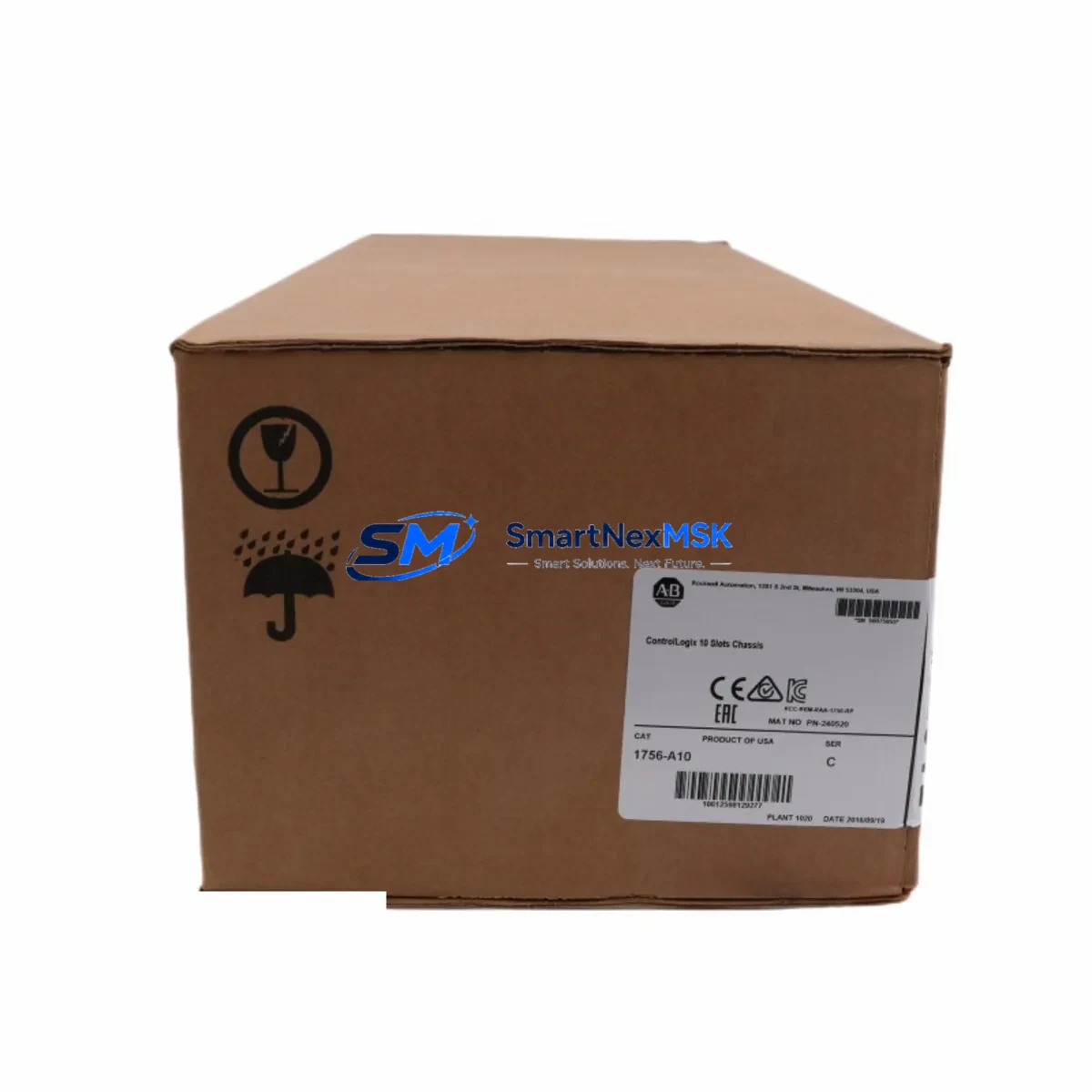
| SKU / Part Number | 1756-A10 |
| Series | ControlLogix (1756 Series) |
| Slot Count | 10 slots |
| Compatible Processors | 1756-L61, 1756-L62, 1756-L63, 1756-L71, 1756-L72, 1756-L73, 1756-L74, 1756-L75 |
| Compatible Power Supplies | 1756-PA72, 1756-PB72, 1756-PA75, 1756-PB75 |
| Backplane Communication | ControlLogix backplane (proprietary high-speed) |
| Communication Module Compatibility | 1756-EN2T, 1756-EN3TR, 1756-CN2, 1756-DNB, 1756-DHRIO |
| Mounting | DIN rail or panel mount |
| Replaces / Upgrades From | 1771 I/O racks (PLC-5), SLC 500 chassis, earlier 1756-Ax chassis revisions |
| Retrofit Recommendation | Direct slot-for-slot replacement within 1756 platform; verify power budget when adding high-draw modules |
| Commissioning Notes | Re-map module slot addresses in Studio 5000 / RSLogix 5000; verify I/O tree after chassis swap |
| Warranty | 12 Months |
Retrofit Planning for Existing Automation Systems
Successful retrofit of a ControlLogix chassis begins well before the physical swap. Engineers must audit the existing control cabinet to document every module currently installed in the legacy rack — including the processor (e.g., 1756-L63 or 1756-L71), analog and digital I/O modules, the 1756-EN2T EtherNet/IP communication adapter, and any specialty modules such as the 1756-M02AE motion module or 1756-HSC high-speed counter. This inventory forms the basis of the new slot assignment plan for the 1756-A10.
Power budget verification is a non-negotiable step. Each module installed in the 1756-A10 draws current from the backplane, supplied by the chassis power supply — typically a 1756-PA72 (120/240 VAC) or 1756-PB72 (24 VDC). Before finalizing the module layout, sum the backplane current draw for all installed modules and confirm it does not exceed the power supply’s rated output. Overlooking this step is a common cause of intermittent faults and unexpected shutdowns after a chassis replacement.
Terminal wiring and field device connections must be carefully preserved during the transition. If the legacy system used a 1771 I/O rack with hard-wired terminal blocks, the retrofit plan should include adapter wiring harnesses or re-termination to 1756-series I/O modules such as the 1756-IB16 (16-point 24 VDC digital input) or 1756-OB16E (16-point electronically fused digital output). For analog signals, the 1756-IF8 (8-channel analog input) and 1756-OF8 (8-channel analog output) are common replacements for legacy analog I/O cards.
Communication protocol migration is another critical planning element. Older systems may rely on Data Highway Plus (DH+) or Remote I/O (RIO) networks. The 1756-DHRIO dual-port DH+/RIO communication module can be installed in the 1756-A10 to maintain backward compatibility with existing HMI panels and remote I/O drops during a phased migration, allowing the facility to transition to EtherNet/IP incrementally without a full cutover. The 1756-CN2 ControlNet adapter similarly supports hybrid network environments where ControlNet infrastructure is already in place.
Module address configuration in Studio 5000 Logix Designer must be updated to reflect the new chassis slot assignments. Any changes to slot numbers will require corresponding updates to the I/O tree in the controller project file, and all affected rungs in the ladder logic or function block diagrams must be verified. HMI screens built in FactoryTalk View SE or ME that reference specific tag addresses tied to I/O slot locations will also require review and update before go-live.
Downtime Control During System Migration
Minimizing production downtime during a chassis retrofit requires a structured migration plan executed during a scheduled maintenance window. The recommended approach is to prepare the replacement 1756-A10 chassis offline — pre-installing all modules, configuring slot assignments, and loading the updated controller project — so that the physical swap in the control cabinet is reduced to a connection and power-up sequence.
Before powering down the existing system, create a full backup of the controller project using RSLogix 5000 or Studio 5000, and export all HMI tag databases and screen configurations. Force tables and current I/O status should be documented to support post-swap verification. If the system includes a redundant controller pair using a 1756-RM2 redundancy module, the switchover procedure must be coordinated to ensure the secondary controller assumes control cleanly before the primary chassis is taken offline.
After installing the 1756-A10 and powering up, perform a systematic I/O verification: confirm each input and output module is recognized in the I/O tree, check communication link status on the 1756-EN2T or 1756-EN3TR adapter, and verify that all field devices are responding correctly. Run the system in program mode before switching to run mode to allow a final logic review. Document the commissioning results and retain them alongside the 12-month warranty certificate for future reference.
Retrofit Support FAQ
Q: Is the 1756-A10 a direct drop-in replacement for other 1756-series chassis?
A: Yes. The 1756-A10 is physically and electrically compatible with all standard 1756-series modules and power supplies. It can replace any 1756-Ax chassis of the same slot count (10 slots) without modification to the modules themselves. Slot address reassignment in the controller project may be required if the previous chassis had a different slot layout.
Q: What wiring changes are needed when replacing a PLC-5 or SLC 500 system with a 1756-A10-based ControlLogix system?
A: PLC-5 and SLC 500 systems use different I/O module form factors and terminal block configurations. Field wiring will need to be re-terminated to the appropriate 1756-series I/O modules. Allen-Bradley offers migration wiring conversion kits for common PLC-5 to ControlLogix transitions. A full I/O point-to-point wiring audit is recommended before the cutover.
Q: How is the 1756-A10 tested before shipment?
A: Each 1756-A10 unit undergoes functional testing prior to shipment, including backplane continuity verification and power rail integrity checks. Units are shipped with original or equivalent protective packaging. A 12-month warranty covers defects in materials and workmanship from the date of delivery.
Q: Can the 1756-A10 support both EtherNet/IP and legacy DH+ communication simultaneously?
A: Yes. By installing both a 1756-EN2T EtherNet/IP adapter and a 1756-DHRIO DH+/RIO module in the 1756-A10 chassis, the system can maintain simultaneous communication on both networks. This is a common configuration during phased migrations where legacy HMI panels or remote I/O drops on DH+ must remain operational while the new EtherNet/IP infrastructure is being commissioned.
© 2026 SMARTNEXMSK. All rights reserved.
Original Source: https://smartnexmsk.com
Contact: sales@smartnexmsk.com | +86 18259474341