Allen-Bradley 1756-EN2F Retrofit-Ready EtherNet/IP Fiber Module for ControlLogix Systems
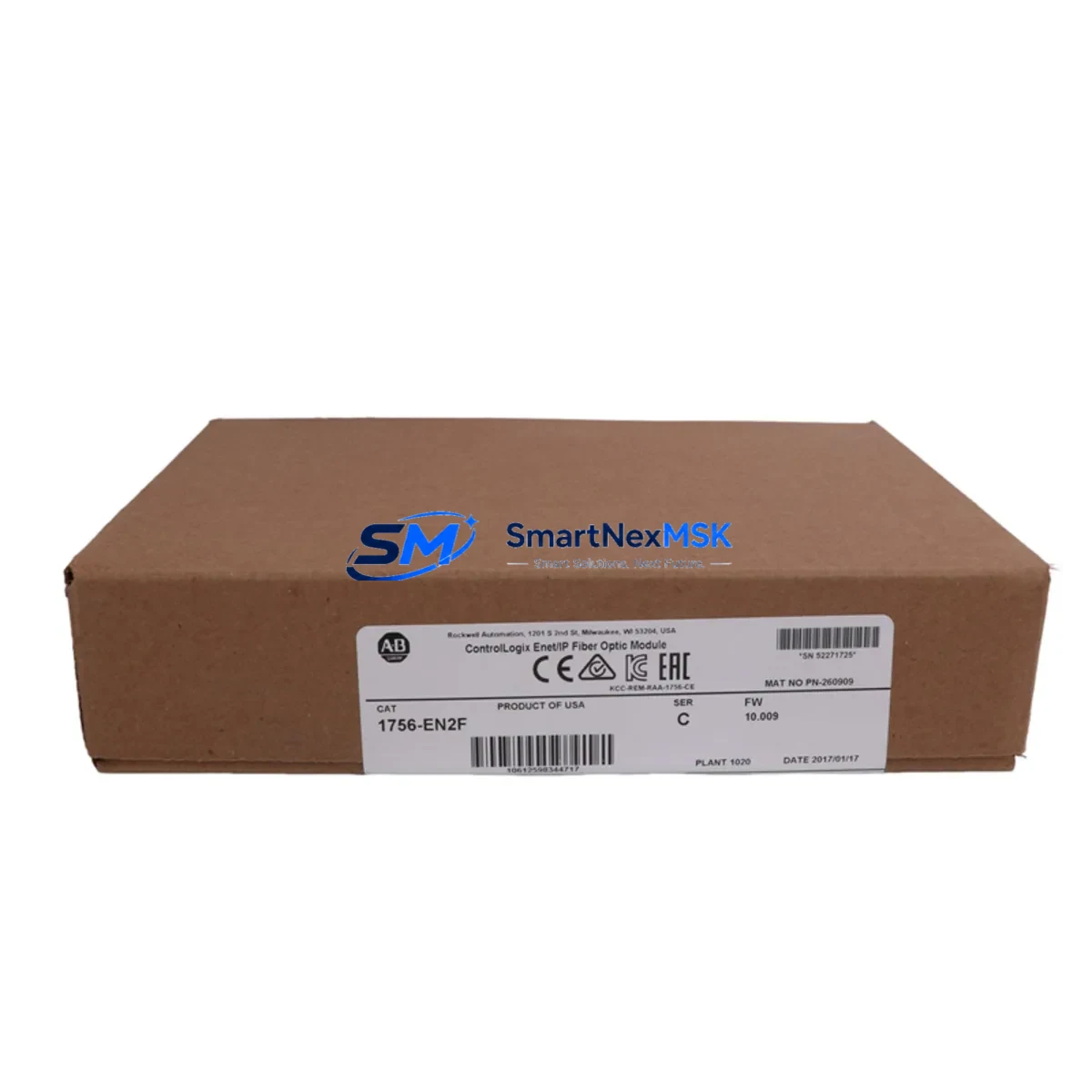
The Allen-Bradley 1756-EN2F is a fiber-optic EtherNet/IP communication module designed for the ControlLogix 1756 chassis platform. As legacy automation infrastructure ages and original Rockwell Automation supply channels tighten, the 1756-EN2F has become one of the most sought-after retrofit and replacement components in industrial control system modernization projects. Whether you are upgrading an aging DCS-linked control cabinet, migrating from a copper-based 1756-ENBT network to a fiber topology, or restoring a production line after an unplanned module failure, the 1756-EN2F delivers the bandwidth, noise immunity, and protocol compatibility required for seamless integration into existing ControlLogix architectures.
This module occupies a single slot in any standard 1756 chassis — including the 1756-A4, 1756-A7, 1756-A10, and 1756-A13 backplane configurations — and communicates over 100 Mbps multimode fiber using standard LC connectors. It supports both Class 1 and Class 3 EtherNet/IP connections, making it fully compatible with Studio 5000 Logix Designer programming environments and legacy RSLogix 5000 project files. When replacing a failed or end-of-life 1756-ENBT or 1756-EN2T copper module, engineers must verify the module slot address assignment in the I/O tree, confirm that the IP address and subnet mask are correctly re-entered via BOOTP/DHCP or the module’s rotary switches, and validate that all CIP connection paths in the controller project remain intact before going online.
Upgrade Compatibility Table
| Parameter | 1756-EN2F (This Module) | 1756-ENBT (Legacy) | 1756-EN2T (Copper Alt.) |
|---|---|---|---|
| Interface Type | 100 Mbps Multimode Fiber (LC) | 10/100 Mbps Copper (RJ45) | 10/100 Mbps Copper (RJ45) |
| Chassis Compatibility | 1756-A4 / A7 / A10 / A13 / A17 | 1756-A4 / A7 / A10 / A13 | 1756-A4 / A7 / A10 / A13 / A17 |
| EtherNet/IP Protocol | Class 1 & Class 3 CIP | Class 1 & Class 3 CIP | Class 1 & Class 3 CIP |
| Max TCP Connections | 256 | 64 | 256 |
| Slot Footprint | 1 Slot | 1 Slot | 1 Slot |
| IP Configuration | BOOTP / DHCP / Rotary Switch | BOOTP / DHCP / Rotary Switch | BOOTP / DHCP / Rotary Switch |
| Retrofit Recommendation | ✅ Direct replacement for 1756-ENBT in fiber environments | ⚠️ End-of-life; limited availability | ✅ Copper alternative if fiber not required |
| Commissioning Note | Re-assign IP; verify CIP path in Studio 5000 | — | Re-assign IP; verify CIP path |
| Warranty | 12 Months | As-is / OEM | 12 Months |
Retrofit Planning for Existing Automation Systems
Successful integration of the 1756-EN2F into a brownfield control system requires a structured pre-installation audit. Begin by documenting the existing backplane layout: record which slots in the 1756 chassis are occupied by the 1756-L73 or 1756-L75 ControlLogix controller, any 1756-IB16 or 1756-OB16E digital I/O modules, analog input cards such as the 1756-IF8, and any existing 1756-DHRIO or 1756-DNB DeviceNet bridge modules that handle legacy field device communication. Understanding the full slot map prevents address conflicts and ensures the new fiber communication module is assigned a logical position that matches the existing Studio 5000 project I/O tree.
Power budget verification is equally critical. The 1756-EN2F draws power from the 1756 chassis backplane, supplied by the installed 1756-PA75 or 1756-PB75 power supply. Before installation, calculate the total backplane current draw across all installed modules and confirm the power supply has sufficient headroom. Overloaded backplanes are a common cause of intermittent communication faults in retrofit projects and are frequently overlooked during rapid replacement scenarios.
For systems that include a PanelView Plus 7 HMI communicating over EtherNet/IP, the HMI’s communication path must be updated to reflect the new module’s IP address after replacement. Failure to update the HMI communication configuration results in loss of operator display data and alarm visibility — a critical gap in process environments. Similarly, if the control system interfaces with a Stratix 5700 or Stratix 8000 managed Ethernet switch, the switch port configuration (VLAN assignment, QoS settings, and port speed) should be verified to ensure compatibility with the fiber transceiver characteristics of the 1756-EN2F.
In systems where the ControlLogix rack communicates upstream to a PlantPAx DCS or a SCADA platform via OPC-DA or OPC-UA, the communication path tag structure in the controller must be preserved exactly. Any change to the module’s slot number or IP address that is not reflected in the OPC server’s tag browser will result in data loss at the supervisory level. Always perform a full tag audit and OPC server reconnection test as part of the commissioning checklist.
Downtime Control During System Migration
Minimizing production downtime during a 1756-EN2F replacement requires a disciplined pre-outage preparation protocol. Before taking the system offline, export a full backup of the Studio 5000 project file (.ACD) and store it on an isolated engineering workstation. Capture a screenshot or export of the current I/O module configuration, including all connection parameters, RPI (Requested Packet Interval) settings, and inhibit states. This baseline ensures that if the replacement module requires re-commissioning from scratch, the original logic and connection topology can be restored without relying on memory or undocumented field wiring.
During the physical swap, label all fiber patch cables before disconnection and photograph the backplane slot layout. The 1756-EN2F uses LC-type fiber connectors; confirm that the plant’s fiber infrastructure terminates in compatible LC patch panels or that appropriate LC-to-SC or LC-to-ST adapters are available on-site. After seating the new module, power up the chassis and allow the module to complete its self-diagnostic cycle — indicated by the MOD and NET status LEDs transitioning from red to green — before attempting to go online with the controller.
Once online, verify that all CIP connections listed in the controller’s I/O tree show a green status. Use the RSLinx Classic or Studio 5000 online diagnostics to confirm that the module’s connection count, packet error rate, and input/output data integrity are within normal parameters. For critical process lines, a parallel hot-standby approach using a 1756-EN2F in a redundant ControlLogix chassis (paired with a 1756-RM2 redundancy module) can eliminate unplanned downtime entirely by allowing seamless controller switchover during the migration window.
Retrofit Support FAQ
Q1: Is the 1756-EN2F a direct drop-in replacement for the 1756-ENBT?
The 1756-EN2F is functionally compatible with the 1756-ENBT in terms of EtherNet/IP protocol support and chassis slot footprint, but it uses a fiber (LC multimode) interface rather than copper (RJ45). If your existing network infrastructure is copper-based, the 1756-EN2T is the closer drop-in replacement. If you are upgrading to a fiber backbone for noise immunity or long-distance runs, the 1756-EN2F is the correct choice. In both cases, the module IP address, CIP connection paths, and Studio 5000 I/O tree must be reconfigured after installation.
Q2: What commissioning steps are required after installing the 1756-EN2F?
After physical installation, assign the module’s IP address using BOOTP/DHCP utility or the onboard rotary switches. Go online with the ControlLogix controller via Studio 5000 and verify that the module appears in the I/O tree with a healthy connection status. Confirm all RPI values are restored, check that the PanelView HMI communication path is updated, and run a full I/O force test on non-critical outputs before returning the system to automatic mode. Document the final IP configuration and slot assignment in the plant’s control system register.
Q3: How do I verify wiring and terminal compatibility during replacement?
The 1756-EN2F does not use field wiring terminals — it connects exclusively via LC fiber patch cables to the plant’s Ethernet fiber infrastructure. Terminal wiring compatibility is relevant for the I/O modules in the same chassis (e.g., 1756-IB16, 1756-OB16E), not for the communication module itself. Ensure that the fiber patch cable length and bend radius comply with the multimode fiber specifications and that the LC connectors are clean and undamaged before insertion.
Q4: What does the 12-month warranty cover, and how is it validated?
All 1756-EN2F units supplied by SMARTNEXMSK carry a 12-month warranty covering manufacturing defects and functional failures under normal operating conditions. Each unit undergoes pre-shipment functional testing, including power-on self-test, LED status verification, and EtherNet/IP communication handshake validation. Warranty claims are processed via sales@smartnexmsk.com with proof of purchase and a fault description. Units showing physical damage from incorrect installation, overvoltage, or environmental exposure outside the module’s rated operating range are not covered under the standard warranty terms.
© 2026 SMARTNEXMSK. All rights reserved.
Original Source: https://smartnexmsk.com
Contact: sales@smartnexmsk.com | +86 18259474341


