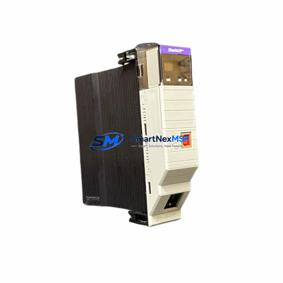
Allen-Bradley 1756-EN2T/D Spare for ControlLogix Automation
The Allen-Bradley 1756-EN2T/D is a Series D EtherNet/IP communication bridge module designed for the ControlLogix 1756 chassis platform. As a critical network interface between the ControlLogix backplane and plant-floor Ethernet infrastructure, this module enables real-time I/O control, peer-to-peer messaging, and HMI connectivity across industrial Ethernet networks. When this module fails or reaches end-of-life, the entire ControlLogix rack loses its primary communication path — resulting in unplanned downtime, production loss, and costly emergency procurement. Maintaining a verified spare of the 1756-EN2T/D in your MRO inventory is a proven strategy for minimizing mean time to repair (MTTR) and sustaining continuous operation in process-critical environments.
This listing provides an original, tested Allen-Bradley 1756-EN2T/D spare module, sourced from authorized channels and verified for firmware compatibility with current ControlLogix L7x and L8x controllers. Each unit undergoes functional testing prior to shipment and is backed by a 12-month warranty covering manufacturing defects and operational failures under normal industrial use conditions.
Spare Maintenance Table
| Parameter | Specification |
|---|---|
| Part Number | 1756-EN2T/D |
| Series | Series D |
| Brand | Allen-Bradley (Rockwell Automation) |
| Module Type | EtherNet/IP Communication Bridge |
| Platform Compatibility | ControlLogix 1756 Chassis (L6x, L7x, L8x controllers) |
| Network Protocol | EtherNet/IP (CIP over Ethernet) |
| Port Configuration | Single RJ-45 10/100 Mbps Ethernet port |
| I/O Connections | Up to 256 CIP connections |
| Backplane Current Draw | 1A @ 5VDC (typical) |
| Operating Temperature | 0°C to 60°C (32°F to 140°F) |
| Mounting | 1756 ControlLogix chassis slot (any slot) |
| Firmware | Compatible with RSLogix 5000 / Studio 5000 v20+ |
| Application Environment | Industrial control panels, process automation, discrete manufacturing |
| Condition | Original, tested before shipment |
| Warranty | 12 Months — covers manufacturing defects and operational failure |
| Maintenance Recommendation | Inspect annually; replace if LED status indicates fault or communication loss |
Maintenance Planning for Continuous Operation
When a 1756-EN2T/D module is flagged for replacement during a scheduled outage or emergency fault isolation, experienced maintenance engineers know that the communication module is rarely the only component requiring attention. A thorough inspection of the surrounding ControlLogix system is essential to prevent repeat failures and ensure a clean return to service.
Begin by verifying the integrity of the 1756-PA75 or 1756-PB75 power supply module — an aging or undersized power supply is a common root cause of intermittent communication faults that are incorrectly attributed to the EN2T module itself. Check output voltage rails under load and inspect the capacitor condition if the unit has been in service for more than five years.
Next, inspect the 1756-A10 or 1756-A17 chassis backplane for physical damage, corrosion on the module connectors, or signs of thermal stress. A compromised backplane can cause the replacement EN2T/D to exhibit the same fault symptoms as the original module, leading to misdiagnosis and extended downtime.
Review the 1756-L73 or 1756-L83E controller module firmware version and project file to confirm that the replacement EN2T/D Series D is correctly mapped in the I/O tree. Series D modules introduced updated CIP connection handling; if the controller project was originally configured for a Series A or B module, a minor configuration update in Studio 5000 may be required.
For plants running distributed I/O over EtherNet/IP, inspect the 1734-AENT or 1734-AENTR POINT I/O adapter modules at remote panels. These adapters maintain their own EtherNet/IP connections to the EN2T bridge; after replacing the bridge module, verify that all remote I/O connections re-establish correctly and that no adapter is stuck in a faulted state.
Check all Ethernet patch cables and managed switch port configurations between the 1756-EN2T/D and the plant network. A faulty RJ-45 connector or an incorrectly configured switch port (duplex mismatch, VLAN misconfiguration) can prevent the new module from establishing reliable CIP connections even when the module itself is fully functional.
If the control cabinet includes a 1756-DNB DeviceNet bridge module or a 1756-CN2 ControlNet bridge for legacy field device connectivity, inspect these modules for fault indicators as well — a network-wide communication event that triggered the EN2T fault may have also stressed adjacent communication modules.
For systems with an integrated PanelView Plus 7 or PanelView 800 HMI, confirm that the HMI communication path to the ControlLogix controller is restored after the EN2T replacement. HMI communication paths are often hardcoded to a specific module IP address; if the replacement module is assigned a different IP, the HMI will fail to connect until the address is updated in the project.
Finally, review the 1492-IFM or 1492-AIFM interface modules and terminal block wiring at the I/O modules in the same chassis. Loose field wiring connections can generate spurious I/O faults that are logged alongside the communication fault, creating a misleading fault history that complicates root cause analysis.
Site Replacement Workflow
Step 1 — Pre-replacement verification: Before removing the faulted 1756-EN2T/D, document the module’s IP address, subnet mask, gateway, and chassis slot assignment from the existing RSLinx or Studio 5000 project. Photograph the front panel LED status for maintenance records.
Step 2 — Safe removal: Place the ControlLogix controller in Program mode to inhibit I/O updates. Remove the faulted EN2T/D module from the chassis slot. Inspect the backplane connector pins for damage or contamination before inserting the replacement unit.
Step 3 — Module configuration: Insert the replacement 1756-EN2T/D into the same chassis slot. Using RSLinx Classic or the module’s built-in BOOTP/DHCP server, assign the same IP address as the original module. This eliminates the need to modify the Studio 5000 project and allows the controller to resume communication immediately upon returning to Run mode.
Step 4 — Connection verification: Return the controller to Run mode and monitor the EN2T/D front panel LEDs. The NET LED should display solid green (link established) and the STS LED should display solid green (normal operation). Verify all remote I/O connections, HMI paths, and peer controller messaging paths are re-established in RSLinx or the Studio 5000 diagnostics.
Step 5 — Documentation and spare replenishment: Log the replacement in the maintenance management system (CMMS) with the module serial number, firmware version, and date of installation. Initiate a purchase order for a replacement spare to restore your MRO buffer stock — a single-unit spare strategy leaves the system vulnerable during the procurement lead time for the next failure event.
Spare Parts Support FAQ
Q1: Is this 1756-EN2T/D compatible with both L7x and L8x ControlLogix controllers?
Yes. The 1756-EN2T/D Series D module is compatible with all current ControlLogix L6x, L7x, and L8x controller families. It is also backward-compatible with older L5x controllers running firmware v16 or later. Confirm the Studio 5000 project firmware version before installation to ensure the module catalog number matches the I/O tree configuration.
Q2: What pre-shipment testing is performed on this spare module?
Each 1756-EN2T/D unit is powered up and tested for backplane communication, Ethernet link establishment, and CIP connection handling prior to shipment. Modules that fail any functional test are quarantined and not listed for sale. A test report is available upon request for quality-critical procurement processes.
Q3: How should this module be stored as a long-term spare?
Store the module in its original anti-static packaging in a climate-controlled environment (10°C to 40°C, relative humidity below 85% non-condensing). Avoid storage near strong electromagnetic fields or corrosive atmospheres. For long-term storage exceeding 24 months, power up the module annually to condition the electrolytic capacitors and verify operational status before returning it to the spare pool.
Q4: What does the 12-month warranty cover, and how is a warranty claim processed?
The 12-month warranty covers manufacturing defects and operational failures under normal industrial operating conditions. It does not cover damage resulting from incorrect installation, overvoltage events, physical impact, or unauthorized modification. To initiate a warranty claim, contact our technical support team with the module serial number, purchase order reference, and a description of the fault symptom. Replacement units are dispatched within 3 business days of claim approval.
© 2026 SMARTNEXMSK. All rights reserved.
Original Source: https://smartnexmsk.com
Contact: sales@smartnexmsk.com | +86 18259474341


