Allen-Bradley 1756-EN2T Retrofit EtherNet/IP ControlLogix Module: Compatible Upgrade for Legacy Control Systems
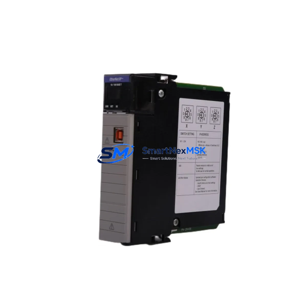
The Allen-Bradley 1756-EN2T is a single-port EtherNet/IP bridge communication module designed for the ControlLogix 1756 chassis platform. As legacy automation infrastructure ages and OEM support for older communication modules is discontinued, the 1756-EN2T has become one of the most sought-after retrofit components for engineers tasked with modernizing distributed control architectures without replacing the entire control cabinet. Whether you are migrating from an older 1756-ENBT or consolidating multiple legacy communication links into a single high-speed EtherNet/IP backbone, the 1756-EN2T provides a direct, slot-compatible upgrade path that preserves existing rack geometry, backplane addressing, and RSLogix 5000 / Studio 5000 program logic.
This module supports 10/100 Mbps full-duplex Ethernet communication and is fully compatible with the ControlLogix 1756 backplane. It integrates seamlessly with existing 1756-L6x and 1756-L7x series controllers, and can coexist in the same chassis alongside I/O modules such as the 1756-IB16, 1756-OB16E, and 1756-IF8, as well as specialty modules including the 1756-DNB DeviceNet Bridge and 1756-CN2 ControlNet Bridge. For systems that require simultaneous EtherNet/IP and ControlNet connectivity, the 1756-EN2T can be installed alongside the 1756-CN2R in a redundant communication topology without chassis modification.
Upgrade Compatibility Table
| Parameter | 1756-EN2T (This Module) | Legacy 1756-ENBT | Notes |
|---|---|---|---|
| Chassis Compatibility | 1756 ControlLogix (all slots) | 1756 ControlLogix (all slots) | Direct slot-for-slot replacement |
| Communication Protocol | EtherNet/IP (CIP) | EtherNet/IP (CIP) | Full protocol compatibility |
| Network Speed | 10/100 Mbps Full-Duplex | 10/100 Mbps | Equivalent throughput |
| Backplane Interface | 1756 Standard Backplane | 1756 Standard Backplane | No backplane rewiring required |
| Module Address Config | Via RSLogix 5000 / Studio 5000 | Via RSLogix 5000 | Re-import I/O tree after swap |
| Power Consumption | ~3.5 W (backplane) | ~4.0 W (backplane) | Verify chassis power budget |
| Firmware Update | Via ControlFLASH | Via ControlFLASH | Match firmware to controller revision |
| HMI Compatibility | PanelView Plus, FactoryTalk View | PanelView Plus, FactoryTalk View | Update IP address in HMI project |
| Replacement Recommendation | Direct drop-in for 1756-ENBT; verify IP and module path in RSLinx Classic | — | |
| Warranty | 12-Month Warranty | Pre-shipment functional test included | ||
Retrofit Planning for Existing Automation Systems
A successful 1756-EN2T retrofit begins well before the module arrives on-site. Engineers should start by auditing the existing 1756 chassis configuration: document every occupied slot, confirm the chassis model (1756-A4, 1756-A7, 1756-A10, or 1756-A17), and calculate the total backplane power draw to ensure the 1756-PA72 or 1756-PB72 power supply has sufficient headroom after the new module is installed. The 1756-EN2T draws approximately 3.5 W from the backplane, which is slightly lower than the older 1756-ENBT, but the power budget must still be verified against all co-installed modules.
Terminal wiring for the Ethernet port uses a standard RJ-45 connector — no special adapter or terminal block is required. However, if the existing network infrastructure uses managed switches with VLAN segmentation or QoS policies, confirm that the switch port assigned to the 1756-EN2T is configured for untagged traffic on the correct VLAN. For systems using a 1783-US5T or similar Stratix unmanaged switch, no additional switch configuration is needed.
Module addressing is handled entirely through RSLogix 5000 or Studio 5000 Logix Designer. After physical installation, open the I/O Configuration tree, delete the old 1756-ENBT entry, and add the 1756-EN2T using the same slot number. Assign the same IP address as the replaced module to avoid downstream communication disruptions with SCADA systems, historian servers, or third-party OPC-DA/UA clients. If the system uses a 1756-L71 or 1756-L73 controller with produced/consumed tags routed through the communication module, verify that the tag path references are updated in the controller properties before going online.
For systems that include a PanelView Plus 7 or PanelView Plus 6 HMI communicating via EtherNet/IP, update the communication path in the FactoryTalk View ME or SE project to reflect the new module’s IP address. If the HMI project references the module by node address rather than IP, no HMI-side changes are required. Similarly, if a 1756-DHRIO module is present in the same chassis for legacy DH+ or Remote I/O communication, its configuration is unaffected by the 1756-EN2T swap.
Systems with analog I/O modules such as the 1756-IF16 or 1756-OF8 should have their channel scaling and alarm setpoints documented before the retrofit, as a controller download following the module swap will overwrite any online edits that were not saved to the project file. Always perform a full project upload from the controller before beginning the physical swap, and store the backup on a secure engineering workstation.
Downtime Control During System Migration
Minimizing unplanned downtime is the primary concern for any live production environment undergoing a communication module retrofit. The recommended approach for a 1756-EN2T swap is a planned maintenance window of 30–60 minutes, during which the following sequence should be followed to protect program logic and maintain field control continuity.
First, place the 1756-L7x or 1756-L6x controller into Program mode via RSLogix 5000 or the keyswitch on the controller front panel. This suspends scan execution but retains all tag data and I/O configuration in controller memory. Next, inhibit the existing communication module in the I/O tree to prevent fault propagation to the controller during the physical swap. Remove the old module from the chassis — the 1756 backplane is hot-swappable, so the controller and other modules remain powered during this step. Insert the 1756-EN2T into the same slot, allow the module to boot (indicated by the OK LED cycling from red to green), and then un-inhibit the module in the I/O tree.
Once the module is online, verify the connection status in RSLinx Classic or the Studio 5000 controller diagnostics. Confirm that all produced and consumed tag connections are re-established, and that any remote I/O adapter modules — such as a 1734-AENT POINT I/O EtherNet/IP adapter or a 1769-L30ER CompactLogix controller acting as a remote rack — have re-connected successfully. Return the controller to Run mode only after all connections show a green status. This sequence typically results in a field control interruption of less than five minutes, with the remainder of the maintenance window used for verification and documentation.
For systems where even brief interruptions are unacceptable, a redundant ControlLogix chassis using a 1756-RM2 redundancy module can be configured to perform a bumpless switchover during the primary chassis maintenance, keeping field outputs energized throughout the swap.
Retrofit Support FAQ
Q1: Is the 1756-EN2T a direct replacement for the 1756-ENBT?
Yes. The 1756-EN2T occupies the same chassis slot, uses the same backplane interface, and supports the same EtherNet/IP (CIP) protocol as the 1756-ENBT. After physical installation, you will need to update the module entry in the RSLogix 5000 or Studio 5000 I/O Configuration tree and confirm the IP address assignment. No terminal rewiring is required.
Q2: What commissioning steps are required after installation?
After inserting the module, verify the OK LED status, confirm the IP address via RSLinx Classic or the module’s web server, update the I/O Configuration tree in your controller project, and perform a controlled download. Test all EtherNet/IP connections — including any remote I/O adapters, HMI communication paths, and SCADA/historian links — before returning the system to automatic operation.
Q3: How do I verify wiring and network compatibility before the swap?
The 1756-EN2T uses a standard RJ-45 Ethernet port. Confirm that the existing Cat5e or Cat6 patch cable is in good condition and that the connected switch port is configured for the correct VLAN and speed/duplex settings. No special terminal block or adapter is required. For systems using fiber-to-copper media converters, verify that the converter’s output speed matches the module’s auto-negotiation settings.
Q4: What does the 12-month warranty cover, and is pre-shipment testing included?
Every 1756-EN2T unit supplied by SMARTNEXMSK undergoes a pre-shipment functional test that verifies backplane communication, Ethernet port integrity, and firmware version. The 12-month warranty covers manufacturing defects and functional failures under normal operating conditions. Units are shipped with test documentation. For warranty claims, contact sales@smartnexmsk.com with your order reference and a description of the observed fault.
© 2026 SMARTNEXMSK. All rights reserved.
Original Source: https://smartnexmsk.com
Contact: sales@smartnexmsk.com | +86 18259474341


