Allen-Bradley 1756-EN2TR/B Retrofit-Ready EtherNet/IP for ControlLogix Systems: Compatible Modernization and Smooth Legacy Upgrade
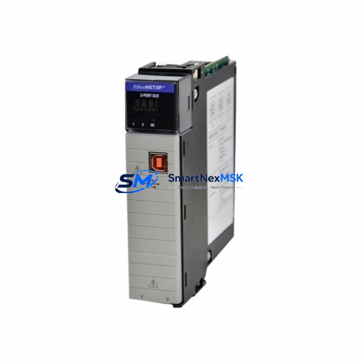
The Allen-Bradley 1756-EN2TR/B is a dual-port EtherNet/IP bridge communication module designed for the ControlLogix 1756 chassis platform. As legacy automation infrastructure ages and original equipment manufacturers discontinue older communication cards, the 1756-EN2TR/B has become one of the most sought-after retrofit solutions for engineers managing aging control panels, distributed I/O networks, and multi-ring EtherNet/IP topologies. Whether you are replacing a failed 1756-ENBT, migrating from a single-port 1756-EN2T, or upgrading a legacy 1756-EN2TR/A revision to the /B variant, this module delivers backward-compatible performance with Device Level Ring (DLR) media redundancy support built in.
The 1756-EN2TR/B occupies a single slot in any standard 1756 ControlLogix backplane, including the 1756-A4, 1756-A7, 1756-A10, and 1756-A13 chassis. It communicates at 100 Mbps full-duplex and supports up to 256 CIP connections, making it suitable for large-scale distributed control architectures where multiple remote I/O drops, drives, and HMI panels share the same EtherNet/IP network segment. The module is fully compatible with Studio 5000 Logix Designer and RSLogix 5000 programming environments, and no firmware changes to the 1756-L7x or 1756-L8x ControlLogix controllers are required when performing a like-for-like slot replacement.
Upgrade Compatibility Table
| Parameter | 1756-EN2TR/B (This Module) | Legacy / Replaced Models |
|---|---|---|
| Form Factor | 1756 ControlLogix single-slot | Same — 1756-ENBT, 1756-EN2T, 1756-EN2TR/A |
| Port Configuration | Dual RJ-45 EtherNet/IP ports | Single port (1756-ENBT, 1756-EN2T) |
| DLR Support | Yes (Device Level Ring) | No (1756-ENBT, 1756-EN2T) |
| Max CIP Connections | 256 | 128 (1756-ENBT) / 256 (1756-EN2T) |
| Communication Speed | 100 Mbps full-duplex | 100 Mbps (same) |
| Backplane Compatibility | 1756-A4 / A7 / A10 / A13 / A17 | Same chassis family |
| Programming Software | Studio 5000 / RSLogix 5000 | RSLogix 5000 (same) |
| Firmware Update Required | No (slot-for-slot replacement) | — |
| IP Address Configuration | BOOTP, DHCP, or static via rotary switch | Same method |
| Commissioning Tool | RSLinx Classic / Studio 5000 | Same |
| Warranty | 12 Months | — |
Retrofit Planning for Existing Automation Systems
A successful retrofit begins well before the module arrives on site. Engineers replacing a 1756-ENBT or 1756-EN2T with the 1756-EN2TR/B should first audit the existing network topology to determine whether the installation will benefit from DLR ring configuration or will continue operating in linear mode. In either case, the IP address, subnet mask, and gateway settings from the outgoing module must be documented and pre-configured on the replacement unit before insertion into the 1756 chassis.
Power budget verification is a critical pre-installation step. The 1756-EN2TR/B draws power from the 1756-PA72 or 1756-PB72 power supply through the backplane. Engineers should confirm that the chassis power supply has sufficient remaining capacity after accounting for all installed modules — including 1756-IB16 digital input modules, 1756-OB16E digital output modules, 1756-IF8 analog input modules, and any 1756-L7x or 1756-L8x controller cards already occupying slots. Exceeding the backplane power budget will cause intermittent faults and communication dropouts that are difficult to diagnose in the field.
Terminal wiring and physical cabling require attention when the existing installation uses managed switches such as the Stratix 5700 or Stratix 2000. The dual-port design of the 1756-EN2TR/B allows direct ring topology wiring without an external switch at the device level, which can simplify cabinet layouts and reduce the number of active network components in the control enclosure. If the legacy installation used a 1756-ENBT with a single uplink to a managed switch, the migration to DLR with the 1756-EN2TR/B will require re-patching the ring ports and updating the DLR supervisor configuration in Studio 5000.
Module slot addressing must be verified in the controller project file. In RSLogix 5000 or Studio 5000, the communication module is referenced by its chassis slot number. If the 1756-EN2TR/B is installed in a different slot than the module it replaces, all I/O tree references, produced/consumed tags, and MSG instruction paths that reference the old slot number must be updated before going online. Failure to update slot addressing is one of the most common causes of communication faults after a module swap.
HMI screen updates may also be required if the plant uses a PanelView Plus 7 or PanelView Plus 6 terminal connected via EtherNet/IP. If the IP address of the communication module changes during the retrofit, the HMI project must be updated to reflect the new target path, and the FactoryTalk View ME or SE application must be re-downloaded to the terminal. Where possible, maintaining the same IP address eliminates this step entirely.
For installations that include a 1756-DNB DeviceNet bridge or a 1756-CN2 ControlNet bridge in the same chassis, the retrofit plan should confirm that these modules are not affected by the EtherNet/IP module replacement. Multi-network chassis configurations require careful slot-by-slot documentation before any module is removed.
Downtime Control During System Migration
Minimizing production downtime during a communication module replacement requires a structured hot-swap or planned-outage approach. For non-redundant ControlLogix systems, the safest method is to schedule the replacement during a planned maintenance window. Before removing the 1756-EN2TR/A or 1756-ENBT, upload the current controller program from the 1756-L7x or 1756-L8x processor to a laptop running Studio 5000 and save a timestamped backup. This preserves all rung logic, tag databases, motion profiles, and produced/consumed tag configurations in the event that the controller enters a faulted state during the swap.
For systems running Redundancy with a 1756-RM2 redundancy module, the EtherNet/IP communication module replacement should be performed on the secondary chassis first, followed by a controlled switchover before replacing the module in the primary chassis. This approach keeps the process running throughout the maintenance window and eliminates unplanned shutdowns.
After inserting the 1756-EN2TR/B, verify the module status LEDs: the NET LED should flash green during IP address acquisition and turn solid green once the module is online. The MOD LED should be solid green. If either LED shows red or amber, check the IP address configuration, confirm the backplane power budget, and verify that the module firmware is compatible with the installed controller firmware revision.
Once the module is online, perform a full I/O tree scan in Studio 5000 to confirm that all remote 1734 POINT I/O adapters, 1756 remote chassis, and drive nodes on the EtherNet/IP network are communicating correctly. Run a short production cycle in manual mode before returning the system to automatic control to verify that all interlocks, permissives, and safety logic are functioning as expected.
Retrofit Support FAQ
Q: Is the 1756-EN2TR/B a direct drop-in replacement for the 1756-EN2TR/A?
A: Yes. The /B revision is backward compatible with the /A revision and occupies the same single slot in any 1756 ControlLogix chassis. No changes to the controller program or I/O tree are required for a same-slot, same-IP-address replacement. The /B revision includes minor firmware and hardware improvements over the /A but is functionally identical from the network and programming perspective.
Q: Can the 1756-EN2TR/B replace a 1756-ENBT or 1756-EN2T in an existing installation?
A: Yes, with minor configuration steps. The 1756-EN2TR/B provides a superset of the functionality of both the 1756-ENBT and 1756-EN2T. The primary differences are the addition of a second Ethernet port and DLR support. If the existing installation uses a single-port linear topology, only one port needs to be connected and the DLR feature can remain unused. The IP address, CIP connection count, and backplane slot assignment should be matched to the outgoing module to minimize reconfiguration.
Q: What commissioning steps are required after installing the 1756-EN2TR/B?
A: After physical installation, configure the IP address using the rotary switches on the module face or via BOOTP/DHCP. Open Studio 5000 or RSLinx Classic and verify that the module appears in the I/O tree with no faults. Confirm all downstream EtherNet/IP devices — including remote I/O adapters, variable frequency drives, and HMI panels — are communicating. Run a controlled test cycle before returning the system to automatic operation. Document the firmware revision and serial number for maintenance records.
Q: What warranty coverage is included with this module?
A: Every 1756-EN2TR/B supplied by SMARTNEXMSK includes a 12-month warranty covering manufacturing defects and functional failures under normal operating conditions. Each unit undergoes pre-shipment functional testing to verify EtherNet/IP communication, DLR ring detection, and backplane interface integrity before dispatch. Warranty claims are supported directly through our technical team at sales@smartnexmsk.com.
© 2026 SMARTNEXMSK. All rights reserved.
Original Source: https://smartnexmsk.com
Contact: sales@smartnexmsk.com | +86 18259474341


