Allen-Bradley 1756-IA16I Spare for ControlLogix Automation: Spare Replacement & Industrial Downtime Risk Control
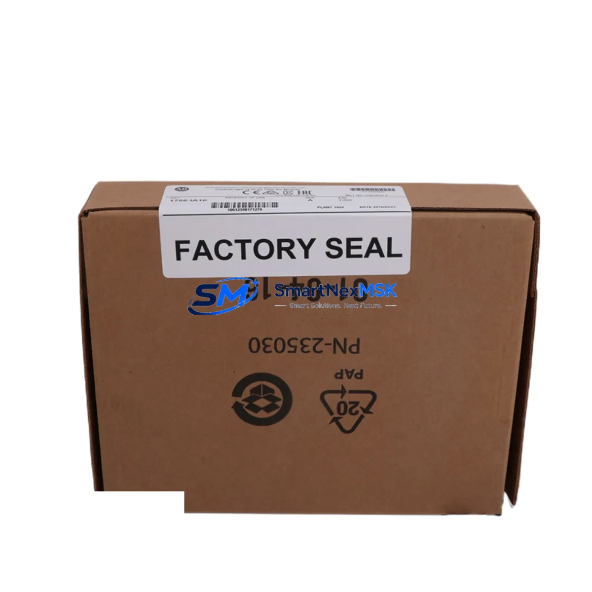
The Allen-Bradley 1756-IA16I is a 16-point, 120V AC isolated digital input module designed for the ControlLogix 1756 platform — one of the most widely deployed programmable automation controller (PAC) architectures in discrete manufacturing, process control, and critical infrastructure. When this module fails or degrades, the consequences extend beyond a single I/O channel: the entire rack’s input integrity is at risk, and unplanned downtime in high-cycle production environments can escalate rapidly. Sourcing a verified, maintenance-ready spare of the 1756-IA16I is the single most effective action a maintenance or procurement engineer can take to protect system uptime.
Each unit supplied by SMARTNEXMSK is tested prior to dispatch, ships with a 12-month warranty, and is traceable to the Allen-Bradley ControlLogix 1756 series specification. Whether you are replenishing a depleted spare parts cabinet, executing a planned shutdown replacement, or responding to an emergency fault, the 1756-IA16I spare is available for immediate order and fast worldwide delivery.
Spare Maintenance Table
| Parameter | Specification |
|---|---|
| Part Number / SKU | 1756-IA16I |
| Brand | Allen-Bradley (Rockwell Automation) |
| Series | ControlLogix 1756 |
| Module Type | 16-Point Isolated Digital Input |
| Input Voltage | 74–132V AC (Nominal 120V AC) |
| Input Current (per point) | Approx. 7 mA @ 120V AC |
| Isolation | Channel-to-channel isolated (16 independent commons) |
| Backplane Compatibility | ControlLogix 1756 chassis (any slot) |
| Communication | ControlLogix backplane (via 1756 chassis) |
| Operating Temperature | 0°C to 60°C (32°F to 140°F) |
| Relative Humidity | 5–95% non-condensing |
| Dimensions (H × W × D) | Standard 1756 single-slot module form factor |
| Approvals | UL, CE, CSA (per original Allen-Bradley certification) |
| Installation | Hot-swap capable in powered 1756 chassis |
| Compatibility Confirmation | Compatible with all 1756-Lxx ControlLogix CPUs and Studio 5000 / RSLogix 5000 programming environments |
| Maintenance Recommendation | Inspect input wiring, terminal blocks, and field device signal levels at each planned shutdown |
| Warranty | 12 Months — covers manufacturing defects and functional failure under normal operating conditions |
| Pre-shipment Testing | Functional verification performed on each unit before dispatch |
| Lead Time | In-stock units ship within 1–3 business days |
Maintenance Planning for Continuous Operation
A disciplined maintenance strategy for any ControlLogix 1756 system goes well beyond replacing the 1756-IA16I in isolation. Maintenance engineers performing a planned or corrective replacement of this isolated digital input module should simultaneously audit the surrounding components that share the same electrical circuit, control cabinet, and backplane environment.
Begin with the 1756-PA75 or 1756-PB75 power supply feeding the chassis. A degraded power supply delivering marginal voltage will cause intermittent input faults that mimic module failure — confirming power supply output under load before condemning the 1756-IA16I is standard diagnostic practice. If the chassis houses a redundant power supply pair, inspect both units and their interconnect.
Next, verify the 1756-TBCH or 1756-TBS6H removable terminal blocks connected to the 1756-IA16I. Loose or corroded terminal connections are a leading cause of false input states in 120V AC circuits. Torque all terminals to specification and inspect for discoloration or heat damage that indicates sustained overcurrent.
For systems using distributed I/O over EtherNet/IP, inspect the 1756-EN2T or 1756-EN3TR communication module in the same chassis. A communication module with degraded network performance can cause the controller to misread input states even when the 1756-IA16I itself is functioning correctly. Check link status, packet error rates, and firmware revision.
In control cabinets where the 1756-IA16I receives signals from field sensors through intermediate relay panels, inspect the interposing relay modules (such as Allen-Bradley 700-HF or equivalent DIN-rail relay bases) for contact wear. Relay contacts in 120V AC circuits typically require replacement after 100,000–500,000 operations depending on load type.
Where signal conditioning is present between field devices and the 1756-IA16I, inspect any signal isolators or signal converters in the loop. Devices such as loop-powered isolators or DIN-rail signal conditioners can introduce signal attenuation or offset that causes the module to misread ON/OFF thresholds, particularly as they age in high-temperature cabinet environments.
For systems with a 1756-L7x or 1756-L8x ControlLogix CPU, confirm that the controller firmware is current and that the I/O configuration in Studio 5000 matches the physical module installed. A firmware mismatch or incorrect electronic keying setting will prevent the replacement 1756-IA16I from going online after installation.
If the control system includes a PanelView Plus HMI (such as the 2711P series) displaying input states from the 1756-IA16I, verify that HMI tag bindings are intact after module replacement and that the operator display reflects live field status correctly before returning the system to production.
Finally, inspect the 1756 chassis backplane itself. In systems with high vibration or thermal cycling, backplane connector pins can develop intermittent contact. If the 1756-IA16I replacement does not resolve the fault, seating all modules firmly and inspecting the chassis for physical damage is the next diagnostic step. Maintaining a spare 1756-A10 or 1756-A17 chassis in the spare parts inventory is recommended for critical production lines.
Site Replacement Workflow
Replacing the 1756-IA16I on-site is a straightforward procedure when the correct spare is available and the replacement workflow is followed systematically. The 1756 ControlLogix platform supports hot-swap module replacement, meaning the module can be removed and inserted while the chassis remains powered — however, the field wiring must be de-energized before disconnecting the terminal block to comply with electrical safety requirements.
Step 1 — Isolate field circuits: De-energize all 120V AC field circuits connected to the 1756-IA16I terminal block. Verify isolation with a calibrated voltage tester at each terminal before proceeding.
Step 2 — Record configuration: In Studio 5000 or RSLogix 5000, note the module’s slot number, electronic keying setting, and RPI (Requested Packet Interval). Take a screenshot or printout for reference during recommissioning.
Step 3 — Remove terminal block: Disconnect the 1756-TBCH or 1756-TBS6H terminal block from the module face. Label the terminal block if multiple modules are being serviced simultaneously to prevent cross-connection.
Step 4 — Extract the faulty module: Press the top and bottom locking tabs and slide the 1756-IA16I out of the chassis slot. Inspect the backplane connector on the module and the chassis slot for damage or contamination.
Step 5 — Install the replacement: Slide the new 1756-IA16I into the same slot until the locking tabs engage. The module will power up and begin communicating with the controller within seconds.
Step 6 — Reconnect and verify: Reattach the terminal block, re-energize field circuits, and confirm in the controller’s I/O tree that the module status is OK (green). Verify that all 16 input points reflect the correct field states before releasing the system to operations.
This workflow minimizes downtime to under 15 minutes for a prepared maintenance team. Keeping a pre-tested 1756-IA16I spare on-site eliminates procurement lead time from the critical path entirely — the difference between a 15-minute recovery and a multi-day production halt.
Spare Parts Support FAQ
Q1: Is this 1756-IA16I unit an original Allen-Bradley module or a third-party replacement?
All 1756-IA16I units supplied by SMARTNEXMSK are original Allen-Bradley (Rockwell Automation) manufactured modules. We do not supply counterfeit, cloned, or third-party substitute modules. Each unit is functionally tested before shipment and covered by a 12-month warranty against manufacturing defects and functional failure.
Q2: How do I confirm compatibility with my existing ControlLogix system before ordering?
The 1756-IA16I is compatible with all ControlLogix 1756 chassis (1756-A4, 1756-A7, 1756-A10, 1756-A13, 1756-A17) and all 1756-series ControlLogix CPUs programmed with RSLogix 5000 or Studio 5000. If your system uses electronic keying, set the keying to “Compatible Module” or “Disable Keying” in the I/O configuration to accept the replacement module. Contact sales@smartnexmsk.com with your CPU catalog number and firmware version if you require compatibility confirmation before purchase.
Q3: What is included in the 12-month warranty and how is a warranty claim processed?
The 12-month warranty covers functional failure and manufacturing defects under normal operating conditions (within the module’s rated voltage, temperature, and humidity specifications). If a unit fails within the warranty period, contact sales@smartnexmsk.com with your order number and a description of the fault. We will arrange return shipping and dispatch a replacement unit. Warranty does not cover damage caused by incorrect installation, overvoltage, or physical impact.
Q4: What is the recommended spare parts stocking strategy for the 1756-IA16I in a critical production environment?
For production lines where the ControlLogix system controls critical processes, we recommend maintaining a minimum of one 1756-IA16I spare per chassis that contains this module type. For facilities with multiple ControlLogix racks or 24/7 continuous operations, a two-unit minimum per site is advisable. Pair the 1756-IA16I spare with a spare 1756-PA75 power supply and a spare 1756-EN2T communication module to cover the three most common single-point failure modes in a ControlLogix rack. SMARTNEXMSK supports long-term supply agreements for customers requiring guaranteed stock availability.
© 2026 SMARTNEXMSK. All rights reserved.
Original Source: https://smartnexmsk.com
Contact: sales@smartnexmsk.com | +86 18259474341


