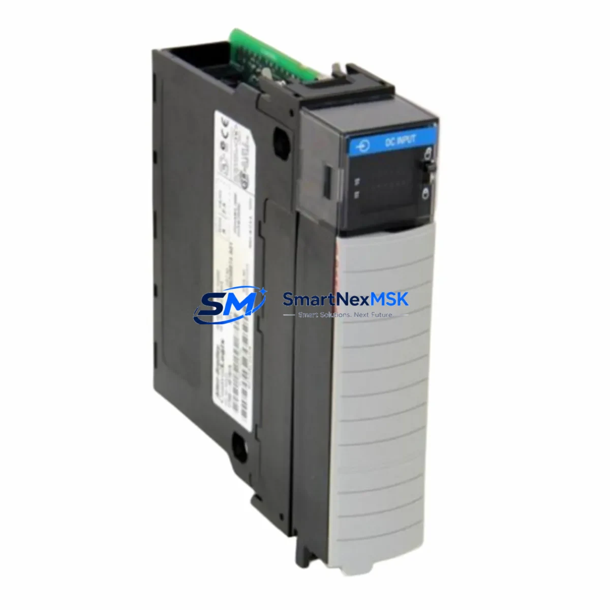
Allen-Bradley 1756-IB16 Retrofit-Ready Digital Input Module for ControlLogix Systems
The Allen-Bradley 1756-IB16 is a 16-point, 24VDC sinking digital input module designed for the ControlLogix 1756 chassis platform. As legacy automation systems reach end-of-life or require capacity expansion, the 1756-IB16 remains one of the most widely specified retrofit components for modernizing existing control architectures without requiring full system replacement. Whether you are replacing a discontinued module, upgrading a control cabinet, or migrating from an older PLC-5 or SLC 500 platform, the 1756-IB16 provides a reliable, wiring-compatible solution that minimizes engineering rework and reduces total downtime during changeover.
Each unit shipped from SMARTNEXMSK inventory undergoes pre-shipment functional verification, including backplane communication checks, input channel continuity testing, and firmware revision confirmation. All modules are supplied with a 12-month warranty covering manufacturing defects and operational failures under normal industrial service conditions.
Upgrade Compatibility Table
| Parameter | 1756-IB16 Specification | Retrofit Notes |
|---|---|---|
| Input Points | 16 x 24VDC Sinking | Direct replacement for 1756-IB16D, 1756-IB16I with wiring review |
| Backplane Interface | ControlLogix 1756 Series Backplane | Compatible with all 1756 chassis sizes (4, 7, 10, 13, 17-slot) |
| Input Voltage Range | 10–31.2 VDC | Verify field device supply voltage before installation |
| Communication | ControlLogix Backplane (proprietary) | No additional communication module required; tag-mapped via Logix Designer |
| Module Addressing | Slot-based, auto-configured in RSLogix 5000 / Studio 5000 | Confirm slot assignment matches existing program tag structure |
| Installation | Hot-swap capable (with chassis support) | Verify chassis firmware supports hot-swap before live replacement |
| Legacy Replacement Path | PLC-5 1771-IB16, SLC 500 1746-IB16 | Requires I/O adapter and program conversion; consult migration guide |
| Warranty | 12-Month Warranty — covers manufacturing defects and operational failures under normal industrial use | |
Retrofit Planning for Existing Automation Systems
Successful integration of the 1756-IB16 into an existing control system begins with a thorough audit of the current cabinet configuration. Engineers should document the 1756-L7x or 1756-L8x ControlLogix controller firmware version, the 1756-PA75 or 1756-PB75 power supply capacity, and the available slot positions within the 1756-A10 or 1756-A17 chassis before ordering replacement modules. Insufficient power budget is one of the most common causes of unexpected behavior after a module swap — the 1756-IB16 draws approximately 2mA from the backplane at 5VDC, but total chassis load must be recalculated when adding or replacing multiple I/O modules simultaneously.
Terminal wiring compatibility should be confirmed against the existing 1756-TBCH or 1756-TBS6H removable terminal block. In most retrofit scenarios, the existing terminal block can be reused without rewiring, provided the field device polarity and common wiring conventions are preserved. Where the original installation used a 1756-IB16D (diagnostic variant), engineers should note that the standard 1756-IB16 does not provide per-channel diagnostics — this functional difference must be reflected in the updated program logic and HMI alarm configuration.
For systems communicating over EtherNet/IP using a 1756-EN2T or 1756-EN3TR communication module, no changes to the network topology are required when replacing a like-for-like 1756-IB16. However, if the retrofit involves migrating from a Remote I/O (RIO) or DH+ network — common in older PLC-5 installations — a 1756-DHRIO bridge module may be required to maintain communication continuity during the transition period. Program tag remapping in Studio 5000 Logix Designer should be completed and verified in offline simulation before any live cutover.
HMI screens built on FactoryTalk View SE or ME platforms should be reviewed for any hardcoded I/O addresses that reference the legacy module’s slot position or tag path. Updating display objects to reference the new tag structure prevents false alarms and operator confusion during the commissioning phase. Where a 1756-IB16 is being added as part of an I/O expansion rather than a direct replacement, the 1756-A4 or 1756-A7 expansion chassis with a 1756-SB power supply provides a cost-effective way to increase input capacity without modifying the primary control rack.
Downtime Control During System Migration
Minimizing production downtime during a ControlLogix I/O module replacement requires careful pre-staging and a structured cutover sequence. The recommended approach is to pre-configure the replacement 1756-IB16 offline using a spare 1756 chassis and a laptop running Studio 5000, verifying that the module profile, electronic keying setting, and input filter times match the existing configuration exactly. Electronic keying should be set to Compatible Module or Disable Keying during initial commissioning to prevent the controller from faulting if minor revision differences exist between the original and replacement unit.
Before removing the original module, export the current controller program and save a timestamped backup to a secure location. If the chassis supports hot-swap, the 1756-IB16 can be removed and reinserted without powering down the rack — however, field devices connected to the module’s input terminals will lose their signal path during the swap interval, so process interlocks should be placed in a safe hold state before proceeding. For systems where hot-swap is not available or not advisable, a planned maintenance window of 15–30 minutes is typically sufficient for a single-module replacement, including wiring verification and initial online diagnostics.
After reinsertion, confirm that the controller transitions from Faulted to Running state and that all 16 input channels report expected states in the I/O tree. Field technicians should walk the panel and verify each connected sensor or switch against the live tag values displayed in Studio 5000 or on the FactoryTalk HMI before releasing the system to production. Document the completed replacement in the site’s maintenance log, including the module serial number, firmware revision, and the name of the technician who performed the work.
Retrofit Support FAQ
Q: Is the 1756-IB16 a direct drop-in replacement for the 1756-IB16D?
A: Physically and electrically, yes — both modules use the same 1756 backplane connector and the same 24VDC sinking input specification. However, the 1756-IB16D includes per-channel diagnostic capability (open-wire and short-circuit detection) that the standard 1756-IB16 does not provide. If your program logic or HMI relies on diagnostic tags from the original module, those references must be removed or remapped before going online with the replacement unit.
Q: What wiring changes are required when replacing a legacy 1746-IB16 (SLC 500) with the 1756-IB16?
A: The 1746-IB16 uses a fixed terminal block on the SLC 500 chassis, while the 1756-IB16 uses a removable 1756-TBCH or 1756-TBS6H terminal block on the ControlLogix chassis. Field wiring must be transferred to the new terminal block, and the program must be converted from SLC 500 ladder logic to Logix 5000 structured text or ladder using Rockwell’s migration tools. Signal commons and power supply references should be verified against the new chassis wiring diagram.
Q: Does SMARTNEXMSK test modules before shipment?
A: Yes. Every 1756-IB16 unit is functionally tested prior to shipment, including backplane communication verification, all 16 input channel checks, and firmware revision confirmation. Units are shipped with original or equivalent packaging and include a 12-month warranty from the date of invoice. A test report is available upon request for critical infrastructure or OEM applications.
Q: Can the 1756-IB16 be used in a redundant ControlLogix system?
A: The 1756-IB16 is compatible with ControlLogix redundancy configurations when installed in a standard I/O chassis connected to the primary and secondary controller chassis via a 1756-RM2 redundancy module. The I/O module itself does not require special configuration for redundancy — the redundancy framework is managed at the controller and communication module level. Confirm your redundancy firmware version supports the module catalog number before deployment.
© 2026 SMARTNEXMSK. All rights reserved.
Original Source: https://smartnexmsk.com
Contact: sales@smartnexmsk.com | +86 18259474341


