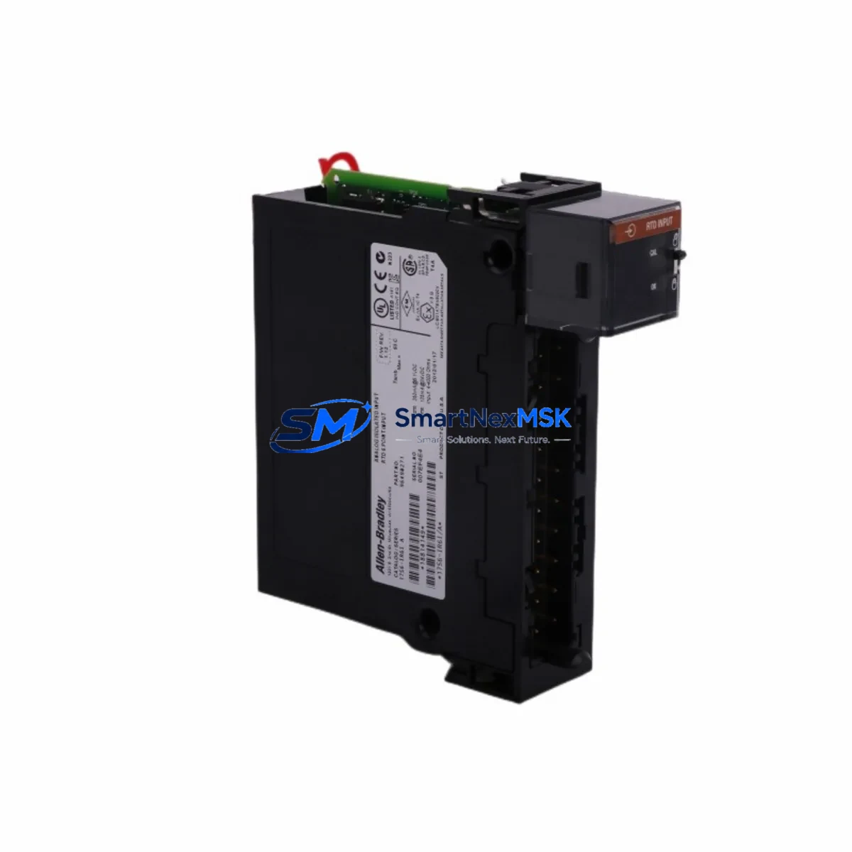
Allen-Bradley 1756-IR6I Spare for ControlLogix Automation
The Allen-Bradley 1756-IR6I is an Isolated RTD/Resistance Input Module designed for the ControlLogix 1756 platform. As a maintenance-ready spare, it enables rapid channel-for-channel replacement in temperature measurement and process monitoring applications — minimizing unplanned downtime and protecting production continuity. Each unit is sourced as an original component, fully tested prior to shipment, and backed by a 12-month warranty.
For maintenance engineers managing aging ControlLogix racks, the 1756-IR6I is a critical line item in any spare parts inventory. Its six isolated input channels support RTD types including PT100, PT1000, Ni120, and resistance inputs up to 1000 Ω, making it suitable for furnace control, HVAC monitoring, boiler systems, and precision process temperature loops. The module communicates over the ControlLogix backplane and is fully compatible with Studio 5000 Logix Designer for configuration and diagnostics.
Spare Maintenance Table
| Parameter | Specification |
|---|---|
| Part Number / SKU | 1756-IR6I |
| Series | ControlLogix 1756 |
| Module Type | Isolated RTD / Resistance Input |
| Input Channels | 6 Isolated Channels |
| Supported RTD Types | PT100, PT1000, Ni120, Cu10, 100–1000 Ω Resistance |
| Input Resolution | 16-bit |
| Backplane Current Draw | 125 mA @ 5 VDC; 2 mA @ 24 VDC |
| Operating Temperature | 0 °C to 60 °C |
| Isolation | Channel-to-channel and channel-to-backplane isolated |
| Compatibility | All 1756 ControlLogix chassis; 1756-A4, A7, A10, A13, A17 |
| Programming Software | Studio 5000 Logix Designer v21+ |
| Certifications | UL, CE, C-Tick |
| Weight | Approx. 260 g |
| Condition | Original, New or Tested Surplus |
| Warranty | 12 Months |
| Pre-shipment Testing | Yes — functional and communication verified |
| Delivery | Global express shipping available |
Maintenance Planning for Continuous Operation
When replacing the 1756-IR6I in a live ControlLogix system, a disciplined maintenance approach requires inspecting the surrounding electrical environment before and after module swap. Begin with the 1756-PA75 or 1756-PB75 power supply — verify output voltage stability and check for ripple that could affect analog accuracy. Inspect the 1756-ENBT or 1756-EN2T EtherNet/IP communication module for firmware currency and network health, as RTD data is typically consumed by SCADA or DCS systems over this path.
Check the 1756-A10 or 1756-A17 chassis backplane for physical damage, corrosion on the module connectors, and proper seating of adjacent modules. If the 1756-IR6I shares a rack with analog output modules such as the 1756-OF8, verify that ground loops are not introduced through shared field wiring. For field wiring integrity, inspect terminal blocks and shielded twisted-pair cables connected to RTD sensors — poor shielding is a leading cause of measurement drift and false alarms.
In systems where the 1756-IR6I feeds temperature data to a PID loop, also review the 1756-L73 or 1756-L85E ControlLogix controller for task scan time and memory utilization. If the system includes a 1756-DNB DeviceNet Bridge or 1756-CN2 ControlNet module, confirm that network traffic is not causing I/O update delays. For installations in high-vibration or high-humidity environments, inspect the 1756-TBCH or 1756-TBS6H wiring arm for terminal looseness and oxidation.
Procurement engineers should also consider stocking the 1756-IT6I2 Isolated Thermocouple Input Module alongside the 1756-IR6I, as both serve temperature measurement roles in the same rack and share similar failure modes. Maintaining a minimum of one spare per critical rack position is recommended for facilities with 24/7 uptime requirements.
Site Replacement Workflow
Step 1 — Pre-replacement verification: Export the existing module configuration from Studio 5000 Logix Designer. Document the module slot number, I/O tree tag assignments, and RTD type configuration for all six channels. Take a photo of field wiring before disconnection.
Step 2 — Safe removal: Place the controller in Program mode. Remove the 1756-IR6I by pressing the top and bottom locking tabs simultaneously and sliding the module out of the chassis. Do not remove the module under power if the chassis does not support hot-swap for this slot configuration — verify with the system integrator’s documentation.
Step 3 — Replacement installation: Insert the new 1756-IR6I into the same slot. The module will be automatically recognized by the ControlLogix controller if the configuration was previously saved. Reconnect field wiring per the documented terminal assignments. Verify RTD sensor polarity and shielding continuity.
Step 4 — Commissioning and validation: Return the controller to Run mode. Monitor the module’s channel status bits in Studio 5000 for any fault codes. Compare live temperature readings against reference instruments or known process values. Log the replacement in the site maintenance record with date, technician ID, and module serial number.
This workflow supports legacy system life extension by enabling like-for-like replacement without PLC program modification, preserving existing tag structures and HMI display mappings.
Spare Parts Support FAQ
Q1: Is the 1756-IR6I compatible with all ControlLogix chassis sizes?
Yes. The 1756-IR6I is compatible with all standard 1756 ControlLogix chassis including the 1756-A4 (4-slot), 1756-A7 (7-slot), 1756-A10 (10-slot), 1756-A13 (13-slot), and 1756-A17 (17-slot). It occupies one slot and communicates via the standard ControlLogix backplane. No hardware modification is required for installation in any of these chassis.
Q2: What pre-shipment testing is performed on each unit?
Every 1756-IR6I unit undergoes functional verification prior to shipment, including backplane communication check, channel input response test, and isolation integrity verification. Units sourced as tested surplus are additionally inspected for physical condition, firmware version, and connector integrity. A test report is available upon request for critical applications.
Q3: How should the 1756-IR6I be stored as a long-term spare?
Store in original anti-static packaging in a dry environment between -40 °C and 85 °C with relative humidity below 95% non-condensing. Avoid proximity to strong magnetic fields or high-voltage equipment. Inspect annually for connector oxidation. For facilities with extended storage requirements beyond 24 months, a functional power-on test is recommended before deployment.
Q4: What is covered under the 12-month warranty?
The 12-month warranty covers manufacturing defects, functional failures under normal operating conditions, and backplane communication faults attributable to the module itself. It does not cover damage from incorrect installation, overvoltage events, or physical mishandling. Warranty claims are processed with return shipping support and replacement or full refund options depending on stock availability.
© 2026 SMARTNEXMSK. All rights reserved.
Original Source: https://smartnexmsk.com
Contact: sales@smartnexmsk.com | +86 18259474341


