Allen-Bradley 1756-IRT8I Spare for ControlLogix Automation: Spare Replacement & Industrial Downtime Risk Control
The Allen-Bradley 1756-IRT8I is an 8-channel isolated RTD and thermocouple input module designed for the Rockwell Automation ControlLogix 1756 platform. In process-critical environments — from petrochemical plants and food processing lines to power generation and discrete manufacturing — this module serves as the primary interface between field temperature sensors and the PLC control loop. When the 1756-IRT8I fails or degrades, temperature feedback is lost, process interlocks may trip, and unplanned downtime begins accumulating costs immediately. Holding a verified original spare on the shelf is the single most effective way to compress mean time to repair (MTTR) and restore production within a single shift.
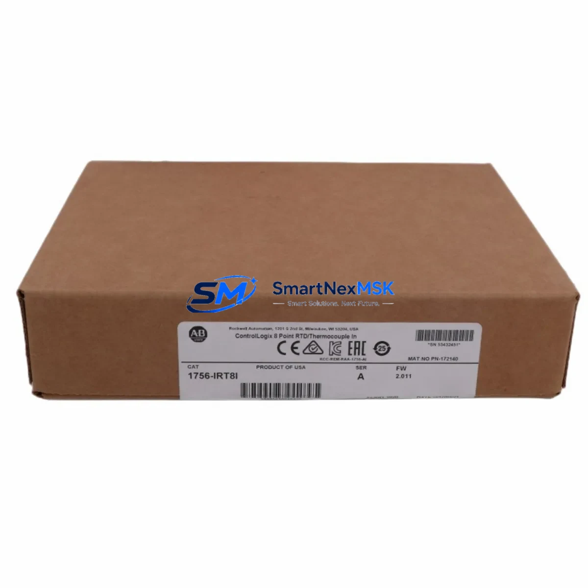
This listing supplies a maintenance-ready, original 1756-IRT8I spare — pre-tested, serialized, and shipped with a 12-month warranty. Every unit undergoes functional verification against Rockwell Automation specifications before dispatch, ensuring that the module you receive is ready for immediate installation without additional bench testing on site.
Spare Maintenance Table
| Parameter | Specification |
|---|---|
| SKU / Part Number | 1756-IRT8I |
| Brand | Allen-Bradley (Rockwell Automation) |
| Series | ControlLogix 1756 |
| Module Type | 8-Channel Isolated RTD / Thermocouple Input |
| Input Channels | 8 (fully isolated, individually configurable) |
| Sensor Types Supported | RTD (Pt100, Pt200, Pt500, Pt1000, Ni120, Cu10) & Thermocouple (J, K, E, T, R, S, B, N, C) |
| Input Resolution | 16-bit |
| Backplane Current Draw | 125 mA @ 5 VDC; 2 mA @ 24 VDC |
| Operating Temperature | 0 °C to 60 °C |
| Storage Temperature | -40 °C to 85 °C |
| Relative Humidity | 5% to 95% non-condensing |
| Chassis Compatibility | All 1756 ControlLogix chassis (4, 7, 10, 13, 17-slot) |
| Firmware Compatibility | RSLogix 5000 / Studio 5000 Logix Designer |
| Certifications | UL, CE, C-Tick |
| Mounting | Hot-swap capable in 1756 chassis |
| Weight | Approx. 350 g |
| Origin | United States |
| Warranty | 12 Months — covers functional failure under normal operating conditions |
| Condition | Original, tested, serialized |
| Shipping | DHL / FedEx Express; global delivery; ESD-safe packaging |
Maintenance Planning for Continuous Operation
Replacing the 1756-IRT8I in a live ControlLogix system is rarely an isolated task. Experienced maintenance engineers know that a module failure is often a symptom of broader stress in the control cabinet — and that a thorough inspection during the replacement window can prevent the next unplanned outage. When pulling the 1756-IRT8I from the chassis, the following components and subsystems should be inspected or tested concurrently.
Backplane and chassis integrity: Inspect the 1756-A17 or equivalent chassis backplane connector for corrosion, bent pins, or thermal discoloration. A degraded backplane can cause intermittent faults on any module seated in the rack, including the 1756-L85E or 1756-L84E controller itself. If the chassis is more than eight years old and operating in a high-vibration or high-humidity environment, consider scheduling a chassis replacement during the next planned outage.
Power supply verification: Confirm that the 1756-PA75 or 1756-PB75 power supply is delivering stable 5 VDC and 24 VDC rails within tolerance. An aging power supply with marginal output can cause soft faults on analog input modules — particularly isolated modules like the 1756-IRT8I that are sensitive to supply ripple. Measure output voltage under load and compare against nameplate ratings.
Field wiring and terminal blocks: RTD and thermocouple wiring is susceptible to ground loops, shield continuity breaks, and connector oxidation. Inspect the 1756-TBCH or equivalent removable terminal block for loose screws, corroded contacts, and correct shielding termination. Verify that thermocouple extension wire grades match the sensor type configured in the module — mismatched extension wire is a common source of offset errors that are often misdiagnosed as module failure.
Adjacent I/O modules: If the 1756-IRT8I shares a chassis with analog output modules such as the 1756-OF8 or digital I/O modules such as the 1756-IB16 or 1756-OB16E, verify that those modules are reporting no faults in the controller’s I/O tree. A single module drawing excessive backplane current can affect neighboring modules.
Communication and network modules: If the ControlLogix system uses EtherNet/IP communication via a 1756-EN2T or 1756-EN3TR module, confirm that the network module firmware is current and that the module is not reporting CIP connection timeouts. Communication faults during a module swap can complicate the replacement process and should be resolved before the maintenance window begins.
Signal isolators and surge protection: In field environments with long cable runs or exposure to electrical noise, signal isolators installed between the field sensors and the 1756-IRT8I input terminals should be inspected for proper operation. Surge protection devices on thermocouple inputs should be tested for continuity and replaced if they have absorbed a transient event.
Fusing and circuit protection: Verify that any fuses protecting the 24 VDC field power circuits associated with the module’s sensor excitation are intact and correctly rated. Blown or degraded fuses are a frequent cause of RTD open-circuit faults that appear as module errors.
Maintaining a documented spare parts list that includes the 1756-IRT8I alongside the power supply, chassis, communication module, and terminal block assembly ensures that your maintenance team can execute a complete cabinet restoration without waiting for additional parts to arrive.
Site Replacement Workflow
Step 1 — Pre-replacement documentation: Before removing the faulty module, capture the current channel configuration from Studio 5000 Logix Designer, including sensor type, engineering unit scaling, filter frequency, and alarm setpoints for all 8 channels. Export the controller project file as a backup. Note the module’s slot number and the chassis serial number for traceability records.
Step 2 — Safe removal: The 1756-IRT8I supports hot-swap in a powered chassis. However, if the process permits, placing the controller in Program mode before removal reduces the risk of nuisance alarms triggered by the brief loss of temperature feedback. Disconnect the removable terminal block first, then release the module locking tab and slide the module out of the chassis slot.
Step 3 — Replacement module verification: Before inserting the new 1756-IRT8I, verify that the catalog number and series letter on the replacement unit match the original. Confirm that the firmware revision is compatible with the controller firmware version in use. If the replacement module carries a different firmware revision, Studio 5000 will prompt for a firmware update or downgrade — plan for this step in your maintenance window.
Step 4 — Installation and configuration download: Insert the replacement module into the same chassis slot. Reconnect the terminal block. The controller will automatically recognize the module and download the stored configuration. Verify that all 8 channels return to normal status in the I/O tree and that process values are within expected ranges before returning the controller to Run mode.
Step 5 — Post-replacement validation: Compare live temperature readings against independent reference measurements or historian trend data to confirm calibration accuracy. Document the replacement in the site maintenance log, including the serial number of the removed module and the replacement unit, the date, and the technician’s name. Return the faulty module for failure analysis if root cause investigation is required.
This workflow applies equally to planned preventive replacements and emergency corrective maintenance. Having a pre-staged 1756-IRT8I spare with a pre-printed terminal block wiring label reduces on-site replacement time to under 30 minutes in most installations.
Spare Parts Support FAQ
Q1: What is the warranty coverage for this 1756-IRT8I spare?
Every 1756-IRT8I supplied through this listing carries a 12-month warranty covering functional failure under normal operating conditions. If the module fails within the warranty period due to a manufacturing or component defect, we will provide a replacement unit or full refund. The warranty does not cover damage caused by incorrect installation, overvoltage events, or physical impact. Warranty claims are processed within 3 business days of receiving the returned unit.
Q2: How do I verify compatibility before installation?
The 1756-IRT8I is compatible with all 1756 ControlLogix chassis variants and all firmware revisions of RSLogix 5000 and Studio 5000 Logix Designer. Compatibility is determined by the chassis series and the controller firmware version. Before installation, confirm the module series letter (Series A, B, or C) matches your existing installed base or is an accepted upgrade path per Rockwell Automation’s product compatibility matrix. If you are unsure, provide your controller catalog number and firmware version and we will confirm compatibility before shipment.
Q3: What pre-shipment testing is performed on each unit?
Each 1756-IRT8I is functionally tested prior to shipment. Testing includes backplane communication verification, channel-by-channel input response testing across the RTD and thermocouple input ranges, and isolation integrity checks. Units that do not pass all test criteria are quarantined and not shipped. A test record is available upon request for quality-critical applications.
Q4: Can you support long-term or blanket spare parts orders for this module?
Yes. For maintenance teams managing multiple ControlLogix installations or operating under a planned preventive maintenance (PPM) program, we support blanket purchase orders, scheduled delivery agreements, and consignment stock arrangements. Long-term supply agreements ensure price stability and guaranteed availability for modules that may be approaching end-of-life or limited availability status. Contact our sales team to discuss volume pricing and delivery scheduling.
© 2026 SMARTNEXMSK. All rights reserved.
Original Source: https://smartnexmsk.com
Contact: sales@smartnexmsk.com | +86 18259474341


