Allen-Bradley 1756-L55M16 Maintenance-Ready Spare ControlLogix: Spare Parts Replacement & Downtime Risk Control
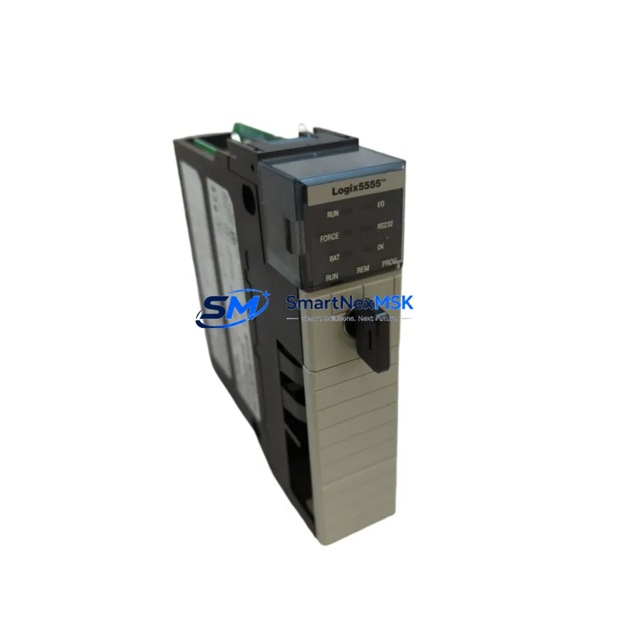
The Allen-Bradley 1756-L55M16 is a ControlLogix series processor module with 7.5 MB of user memory, designed for high-availability industrial automation environments. As a maintenance-ready spare, the 1756-L55M16 supports rapid slot-for-slot replacement within any 1756 ControlLogix chassis, enabling maintenance engineers to restore system operation with minimal downtime. Whether held as a cold standby in a spare parts cabinet or deployed as part of a planned preventive maintenance rotation, this processor module is a critical asset in any industrial control system lifecycle strategy.
Original units are tested prior to dispatch, shipped with full configuration documentation support, and backed by a 12-month warranty. Long-term supply availability is maintained to support aging ControlLogix installations and extended system lifecycles beyond OEM production windows.
Spare Maintenance Table
| Parameter | Specification |
|---|---|
| Part Number / SKU | 1756-L55M16 |
| Brand | Allen-Bradley (Rockwell Automation) |
| Series | ControlLogix 1756 |
| Product Type | PLC Processor Module |
| User Memory | 7.5 MB |
| Chassis Compatibility | 1756 ControlLogix Chassis (all slot widths) |
| Communication | EtherNet/IP, ControlNet, DeviceNet (via adapter modules) |
| Power Supply Compatibility | 1756-PA72, 1756-PB72, 1756-PA75, 1756-PB75 |
| Operating Temperature | 0°C to 60°C |
| Installation | Hot-swap capable within 1756 chassis |
| Origin | United States |
| Condition | Original / Genuine |
| Warranty | 12 Months |
| Pre-shipment Testing | Yes – functional verification before dispatch |
| Typical Application | Discrete manufacturing, process control, batch automation, utilities |
| Maintenance Scenario | Planned replacement, emergency swap, cold standby, lifecycle extension |
Maintenance Planning for Continuous Operation
When replacing the 1756-L55M16 processor in a live ControlLogix system, a thorough inspection of the surrounding control cabinet is essential to prevent repeat failures and ensure full system restoration. Maintenance engineers should begin by verifying the chassis power supply — units such as the 1756-PA72 or 1756-PB72 should be checked for output voltage stability and capacitor aging, as an under-voltage condition can corrupt processor memory during boot.
The 1756-A10 or 1756-A17 chassis backplane should be inspected for physical damage, connector oxidation, and secure module seating. A faulty backplane can cause intermittent communication faults that mimic processor failure. Adjacent I/O modules — including 1756-IB16 digital input and 1756-OB16E digital output modules — should be verified for correct field wiring, blown fuses, and LED diagnostic status before the new processor is brought online.
Communication infrastructure deserves equal attention. If the system uses EtherNet/IP, the 1756-EN2T or 1756-EN2TR communication module should be checked for firmware compatibility with the replacement processor firmware version. For legacy ControlNet topologies, the 1756-CNB or 1756-CNBR bridge module should be inspected for coaxial tap integrity and network scheduling conflicts.
Signal integrity components are frequently overlooked during processor swaps. Inline signal isolators on analog I/O loops — particularly on 4–20 mA process signals feeding 1756-IF16 analog input modules — should be tested for drift and isolation resistance. Terminal blocks and 1492-series wiring systems should be inspected for loose terminations, especially in high-vibration environments. Fuse holders on 24 VDC field power rails should be checked and replaced as part of the maintenance window.
For systems with operator interface requirements, the associated PanelView Plus HMI terminal should be verified for communication path integrity after the processor replacement, as IP address conflicts or RSLinx Classic driver mismatches can prevent HMI reconnection. Where redundancy modules such as the 1756-RM2 are installed, the redundancy configuration should be validated post-swap to confirm primary/secondary role assignment is correct.
Maintaining a structured spare parts inventory that includes the 1756-L55M16 alongside its associated power supplies, communication adapters, and I/O modules significantly reduces mean time to repair (MTTR) and supports long-term system availability for aging ControlLogix installations.
Site Replacement Workflow
Step 1 – Pre-replacement verification: Confirm the replacement 1756-L55M16 firmware version matches or is compatible with the existing project file. Use RSLogix 5000 or Studio 5000 to export the current program and verify the processor series letter (Series B or C) matches the installed unit.
Step 2 – Safe shutdown: Place the system in program mode via the keyswitch or software command. Notify operators and downstream systems. Document the current I/O status and any active alarms before de-energizing the chassis slot.
Step 3 – Module extraction and installation: Remove the faulty 1756-L55M16 by releasing the top and bottom locking tabs. Insert the replacement module firmly until the backplane connector is fully seated. The ControlLogix chassis supports hot-swap at the processor slot — however, a controlled shutdown is recommended for first-time replacements to avoid backplane transients.
Step 4 – Program restore and go-live: Download the verified project file to the new processor. Confirm all I/O modules are recognized and in run mode. Verify communication paths to remote I/O racks, HMI terminals, and SCADA systems. Perform a controlled system restart and monitor for 15–30 minutes before returning to full production.
Step 5 – Documentation update: Record the replacement date, firmware version, and unit serial number in the maintenance log. Update the spare parts inventory to trigger reorder of a replacement cold-standby unit.
Spare Parts Support FAQ
Q1: Is the 1756-L55M16 still available as a new original unit, or only as refurbished stock?
We supply original Allen-Bradley 1756-L55M16 units sourced through authorized industrial distribution channels. Each unit undergoes pre-shipment functional testing. Condition and provenance documentation is available upon request. Contact sales@smartnexmsk.com for current stock status.
Q2: How do I confirm compatibility between the 1756-L55M16 and my existing ControlLogix project file?
Compatibility is determined by processor series letter, firmware revision, and user memory requirements. Open your project in Studio 5000 or RSLogix 5000 and check the controller properties for the target processor type. The 1756-L55M16 (7.5 MB) must meet or exceed the memory footprint of your compiled project. Our technical team can assist with compatibility verification before shipment.
Q3: What is included in the 12-month warranty, and what does the pre-shipment test cover?
The 12-month warranty covers manufacturing defects and functional failure under normal operating conditions. Pre-shipment testing includes power-on verification, backplane communication check, memory integrity scan, and firmware version confirmation. A test report is available upon request. Warranty claims are processed via sales@smartnexmsk.com with a standard RMA procedure.
Q4: Can you support long-term or blanket orders for 1756-L55M16 as part of a site-wide spare parts program?
Yes. We support scheduled delivery agreements, blanket purchase orders, and multi-site spare parts programs for ControlLogix processors and associated modules. Long-term supply planning helps maintenance teams maintain buffer stock without capital overcommitment. Contact our team to discuss volume pricing and delivery scheduling.
© 2026 SMARTNEXMSK. All rights reserved.
Original Source: https://smartnexmsk.com
Contact: sales@smartnexmsk.com | +86 18259474341


