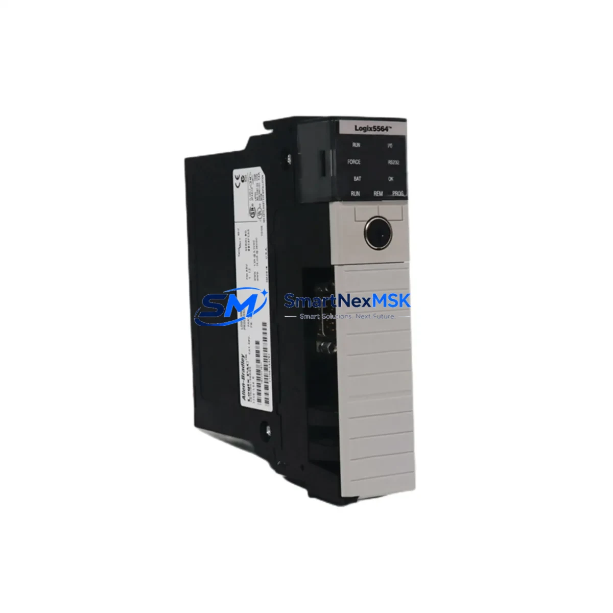
Allen-Bradley 1756-L64 Retrofit-Ready PLC Processor for ControlLogix Systems
The Allen-Bradley 1756-L64 (Logix5564) is a high-performance ControlLogix processor designed for demanding industrial automation environments. With 8 MB of user memory and support for up to 250 I/O modules across multiple chassis, this processor has served as the backbone of countless process control, motion control, and safety-integrated systems across manufacturing, oil & gas, water treatment, and automotive sectors. As legacy installations age and OEM support windows close, the 1756-L64 has become one of the most actively sought retrofit and replacement processors in the ControlLogix platform.
Whether you are replacing a failed unit, upgrading from an earlier Logix5550 or Logix5555 processor, or migrating a complete control cabinet from a legacy SLC 500 or PLC-5 architecture, the 1756-L64 provides a proven, cost-effective path to system continuity. Our inventory is sourced from verified industrial channels, fully tested prior to shipment, and backed by a 12-month warranty covering hardware defects and functional failures under normal operating conditions.
Upgrade Compatibility Table
| Parameter | Details |
|---|---|
| SKU / Catalog Number | 1756-L64 |
| Processor Series | ControlLogix (Logix5564) |
| User Memory | 8 MB |
| Backplane Interface | 1756 ControlLogix Chassis (1756-A4, 1756-A7, 1756-A10, 1756-A13, 1756-A17) |
| Communication Ports | USB (programming), EtherNet/IP via 1756-ENBT or 1756-EN2T modules |
| Replaces / Upgrades From | 1756-L55, 1756-L60, 1756-L61, 1756-L62, 1756-L63 |
| Compatible Programming Software | Studio 5000 Logix Designer v21+, RSLogix 5000 v16–v20 |
| Power Supply Compatibility | 1756-PA72, 1756-PB72, 1756-PA75, 1756-PB75 |
| Installation Requirement | Slot 0 recommended; chassis must be powered down during swap |
| Firmware Upgrade | Required if replacing older firmware revision; use ControlFLASH utility |
| Warranty | 12 Months — covers hardware defects and functional failures |
| Pre-Shipment Testing | Full functional test performed; firmware loaded to customer-specified revision on request |
Retrofit Planning for Existing Automation Systems
A successful 1756-L64 retrofit begins well before the replacement unit arrives on site. Engineers must first audit the existing chassis configuration — identifying the rack model (commonly a 1756-A10 or 1756-A17), the installed power supply (such as a 1756-PA72 or 1756-PB72), and the full complement of I/O and communication modules occupying each slot. Typical installations include a mix of 1756-IB16 digital input modules, 1756-OB16E digital output modules, 1756-IF8 analog input modules, and 1756-OF8 analog output modules. Each of these modules must be confirmed compatible with the firmware revision loaded on the replacement 1756-L64.
Communication architecture is equally critical. Many legacy ControlLogix systems rely on a 1756-ENBT EtherNet/IP bridge module or a 1756-CNB ControlNet bridge to connect the processor to remote I/O racks, SCADA systems, or HMI panels. If the existing network uses ControlNet, verify that the 1756-CNB module firmware is compatible with the new processor revision. For systems using DeviceNet, a 1756-DNB scanner module may be present and must be re-commissioned after the processor swap. EtherNet/IP-based systems using a 1756-EN2T module are generally more straightforward to migrate, as IP addressing and connection parameters are stored in the module itself rather than the processor.
Before removing the existing processor, export a full backup of the RSLogix 5000 or Studio 5000 project file, including all controller tags, program routines, motion groups, and produced/consumed tag configurations. If the system includes a PanelView Plus HMI communicating via EtherNet/IP, document all FactoryTalk View ME application paths and verify that the HMI project references the correct processor IP address and controller tag names. A mismatch in tag names or data types between the old and new processor project will cause HMI communication faults immediately upon startup.
For systems migrating from a legacy PLC-5 or SLC 500 platform to ControlLogix using the 1756-L64 as the target controller, Rockwell Automation’s Migration Assistant tool can assist with ladder logic conversion. However, manual review of all I/O addressing, timer presets, counter accumulations, and PID loop parameters is strongly recommended before going live. Terminal block wiring on 1756-series I/O modules uses a different pitch and connector style than older 1771 or 1746 I/O modules, so field wiring adaptation may require new terminal blocks or interface cables.
Downtime Control During System Migration
Minimizing unplanned downtime during a 1756-L64 processor swap requires a structured pre-outage checklist and a clearly defined rollback plan. Begin by scheduling the swap during a planned maintenance window, coordinating with production scheduling to ensure the affected line or process unit is safely isolated. Place all field devices in a safe state — confirm that pneumatic actuators are de-energized, motor starters are locked out, and any safety relay modules such as the 1756-LSP Safety Partner are in a known safe condition before removing the processor from the chassis.
The physical swap itself takes under five minutes: power down the chassis, remove the existing processor from Slot 0, insert the replacement 1756-L64, and restore power. The processor will boot to the factory default state if no SD card or CompactFlash memory card is present. Load the previously backed-up project file via USB using Studio 5000 or RSLogix 5000, verify the firmware revision matches the project requirements, and perform a controlled download. Once the download is complete, switch the processor to RUN mode and monitor the I/O tree for any module faults. Address any 1756-ENBT or 1756-EN2T connection timeouts by cycling the communication module or verifying IP configuration.
If the system uses produced and consumed tags shared with other ControlLogix controllers across a ControlNet or EtherNet/IP network, verify that all peer controllers re-establish their connections within the expected timeout window. A brief inhibit-and-re-enable cycle on the consumed tag connections from the peer controllers will force reconnection without requiring a full program download on those systems. This approach preserves the original program logic on all peer controllers and keeps the broader control network operational throughout the migration.
Retrofit Support FAQ
Q1: Is the 1756-L64 a direct drop-in replacement for the 1756-L63 or 1756-L62?
Yes, the 1756-L64 is physically and electrically compatible with all standard 1756 ControlLogix chassis and power supplies. It occupies a single chassis slot and uses the same backplane interface as earlier Logix5560 and Logix5563 processors. The primary difference is increased user memory (8 MB vs. 4 MB on the L62 and 2 MB on the L61). Your existing RSLogix 5000 or Studio 5000 project file can be downloaded directly to the 1756-L64 after a firmware revision check.
Q2: What firmware revision should I request, and how is it loaded?
We can pre-load the 1756-L64 to your specified firmware revision prior to shipment upon request — please provide your current project’s firmware version when ordering. On-site firmware updates can be performed using the ControlFLASH utility via USB connection. We recommend matching the firmware revision exactly to your existing project to avoid compatibility warnings during download.
Q3: How do I verify wiring and I/O module compatibility before the swap?
All 1756-series I/O modules (digital, analog, and specialty) are compatible with the 1756-L64 regardless of the processor being replaced, provided the module firmware is current. Review the I/O tree in your existing project file and confirm that each module’s catalog number and revision are listed in the 1756-L64’s compatible module list in the Studio 5000 Add-On Profile library. Terminal wiring on existing 1756-series I/O modules does not need to be changed — only the processor itself is swapped.
Q4: What does the 12-month warranty cover, and what is the claims process?
Our 12-month warranty covers all hardware defects and functional failures under normal industrial operating conditions from the date of shipment. If the unit fails within the warranty period, contact us at sales@smartnexmsk.com with your order number and a description of the fault. We will arrange a replacement unit or repair at no additional cost. Pre-shipment functional testing documentation is available upon request and can be provided as part of your incoming inspection records.
© 2026 SMARTNEXMSK. All rights reserved.
Original Source: https://smartnexmsk.com
Contact: sales@smartnexmsk.com | +86 18259474341


