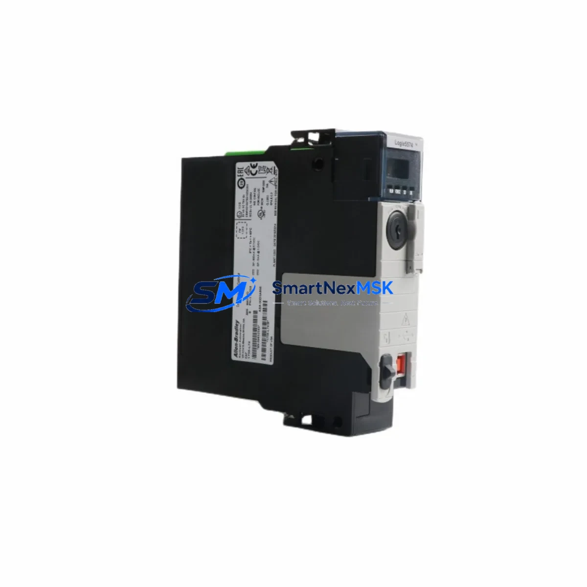
Allen-Bradley 1756-L74 Maintenance-Ready Spare for ControlLogix Automation
The Allen-Bradley 1756-L74 is a high-performance ControlLogix L7x series programmable logic controller featuring 16 MB of user memory and dual Ethernet ports, designed for demanding industrial automation environments. As a maintenance-ready original spare, the 1756-L74 is a critical asset for maintenance engineers managing continuous production lines, process control systems, and safety-critical automation architectures where unplanned downtime carries significant operational and financial risk.
Whether you are executing a planned shutdown, responding to an emergency fault, or building a strategic spare parts inventory for aging ControlLogix infrastructure, the 1756-L74 provides a direct, firmware-compatible replacement that eliminates the need for program re-engineering or hardware reconfiguration. Each unit is sourced from verified supply channels, pre-shipment tested, and backed by a 12-month warranty — giving procurement engineers the confidence to stock this module as a long-term operational asset.
Spare Maintenance Table
| Parameter | Specification |
|---|---|
| SKU / Part Number | 1756-L74 |
| Brand | Allen-Bradley (Rockwell Automation) |
| Series | ControlLogix L7x |
| User Memory | 16 MB |
| I/O Capacity | Up to 128,000 I/O points |
| Communication Ports | Dual EtherNet/IP (built-in) |
| Backplane Compatibility | 1756 ControlLogix Chassis (all slot counts) |
| Power Supply Compatibility | 1756-PA72, 1756-PB72, 1756-PA75, 1756-PB75 |
| Operating Voltage | 24 VDC (backplane powered) |
| Operating Temperature | 0°C to 60°C |
| Firmware | Compatible with Studio 5000 / RSLogix 5000 |
| Origin | USA |
| Condition | Original, Pre-shipment Tested |
| Warranty | 12 Months |
| Application Environment | Discrete, Process, Motion, Safety Control |
| Replacement Compatibility | 1756-L71, 1756-L72, 1756-L73, 1756-L75 (same chassis) |
Maintenance Planning for Continuous Operation
When replacing the 1756-L74 in a live ControlLogix system, a disciplined maintenance engineer will not stop at the controller itself. The surrounding infrastructure must be inspected and validated to ensure the replacement does not introduce new failure points or mask pre-existing degradation.
Begin with the 1756-PA72 or 1756-PB72 power supply module — a failing or under-spec power supply is one of the most common root causes of controller faults and memory corruption. Verify output voltage stability under load before inserting the replacement 1756-L74. Next, inspect the 1756 ControlLogix chassis backplane for physical damage, corrosion on the backplane connector, or signs of thermal stress, particularly in high-cycle environments.
Review all 1756-EN2T or 1756-EN3TR EtherNet/IP communication modules in the chassis. A controller swap is the ideal moment to confirm firmware versions, IP address assignments, and network topology documentation are current. Similarly, inspect any 1756-DNB DeviceNet bridge modules or 1756-CN2 ControlNet modules that share the backplane — these are often overlooked during emergency replacements and can cause post-restoration communication faults.
On the I/O side, audit 1756-IB16 digital input modules and 1756-OB16E digital output modules for blown fuses, field wiring integrity, and terminal block torque. For analog loops, verify 1756-IF16 analog input modules for signal drift and calibration status. If the system includes motion control, confirm that 1756-M02AE servo drive interface modules and associated drive parameters are intact and undisturbed.
Do not overlook the 1756-EWEB EtherNet/IP web server module if remote monitoring is in use, and verify that any 1492 terminal block assemblies connected to I/O modules are properly torqued and free of oxidation. For systems with safety functions, confirm that 1756-L7S GuardLogix safety controller configurations and safety task integrity are unaffected by the maintenance event. Finally, if an PanelView Plus 7 HMI is connected via EtherNet/IP, validate communication path restoration after the controller is back online.
Site Replacement Workflow
Step 1 — Pre-replacement backup: Using Studio 5000 or RSLogix 5000, upload and archive the current controller program, including all tag databases, motion profiles, and safety task configurations. Store the backup on a secure, version-controlled network location — not solely on the controller’s SD card.
Step 2 — Power isolation: Follow site LOTO (Lockout/Tagout) procedures. De-energize the 1756 chassis via the power supply disconnect. Confirm zero-energy state with a calibrated voltage tester before touching any backplane components.
Step 3 — Module extraction: Remove the faulty 1756-L74 by pressing the top and bottom locking tabs simultaneously and sliding the module straight out. Inspect the backplane connector on the chassis for bent pins or debris before inserting the replacement unit.
Step 4 — Replacement insertion: Insert the new 1756-L74 into the same chassis slot. Ensure the module seats fully and the locking tabs engage. Restore power and observe the module status indicators — the RUN LED should illuminate green after successful firmware initialization.
Step 5 — Program restore and validation: Download the archived program to the replacement controller. Verify all I/O connections, communication paths, and HMI data links are restored. Run a controlled test cycle before returning the system to full production.
This workflow minimizes mean time to recovery (MTTR), preserves system compatibility, and ensures the replacement 1756-L74 is fully validated before resuming operations — reducing the risk of secondary faults caused by an incomplete restoration.
Spare Parts Support FAQ
Q1: Is the 1756-L74 compatible with my existing ControlLogix chassis and I/O modules?
Yes. The 1756-L74 is fully compatible with all 1756 ControlLogix chassis sizes (4, 7, 10, 13, and 17 slots) and all standard ControlLogix I/O, communication, and motion modules. No hardware reconfiguration is required when replacing a same-series controller. Firmware version alignment with your Studio 5000 project should be confirmed prior to download.
Q2: What testing is performed before shipment?
Each 1756-L74 unit undergoes pre-shipment functional testing including power-on self-test (POST) verification, backplane communication check, and Ethernet port validation. Units that do not pass all test criteria are not shipped. A test report is available upon request for critical infrastructure procurement.
Q3: How should I manage 1756-L74 spare inventory for aging ControlLogix systems?
For systems running ControlLogix L7x controllers in production-critical roles, industry best practice recommends maintaining at least one cold spare per site and one warm spare (pre-programmed with the current project) for facilities with multiple chassis. Given the 1756-L74’s end-of-life trajectory, early procurement of verified original spares is strongly advised to avoid sourcing risk as market availability tightens.
Q4: What does the 12-month warranty cover?
The 12-month warranty covers manufacturing defects, functional failures under normal operating conditions, and DOA (dead-on-arrival) units. Warranty claims are processed with priority support, including advance replacement options for production-critical applications. Physical damage caused by incorrect installation, overvoltage, or environmental non-compliance is excluded. Contact our technical team for warranty claim initiation.
© 2026 SMARTNEXMSK. All rights reserved.
Original Source: https://smartnexmsk.com
Contact: sales@smartnexmsk.com | +86 18259474341


