Allen-Bradley 1756-L83E Spare for ControlLogix Automation
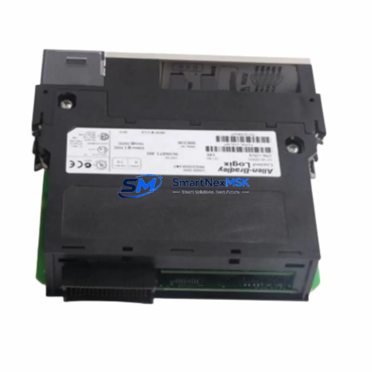
The Allen-Bradley 1756-L83E is a high-performance ControlLogix L8 series PLC processor designed for demanding industrial automation environments. As a maintenance-ready original spare, the 1756-L83E supports rapid replacement in 1756 chassis-based control systems, minimizing unplanned downtime and protecting production continuity. Whether you are managing a scheduled overhaul, responding to an emergency fault, or building a strategic spare parts inventory, the 1756-L83E delivers the processing power, memory capacity, and EtherNet/IP connectivity required to restore full system operation without re-engineering your control architecture.
The 1756-L83E features 8 MB of user memory and an integrated dual-port EtherNet/IP interface, making it a direct fit for ControlLogix systems running Studio 5000 Logix Designer. Its compatibility with the full 1756 chassis family — including the 1756-A4, 1756-A7, 1756-A10, and 1756-A17 — means maintenance teams can deploy this processor across multiple control cabinets without platform changes. Each unit is tested prior to shipment and covered by a 12-month warranty, giving procurement engineers confidence in long-term supply reliability.
Spare Maintenance Table
| Parameter | Specification |
|---|---|
| Part Number / SKU | 1756-L83E |
| Brand | Allen-Bradley (Rockwell Automation) |
| Series | ControlLogix L8 |
| Product Type | PLC Processor Module |
| User Memory | 8 MB |
| Communication Interface | Dual-port EtherNet/IP (integrated) |
| Chassis Compatibility | 1756-A4, 1756-A7, 1756-A10, 1756-A17 |
| Programming Software | Studio 5000 Logix Designer v21+ |
| Power Supply Compatibility | 1756-PA72, 1756-PB72, 1756-PA75, 1756-PB75 |
| Operating Temperature | 0°C to 60°C |
| Mounting | 1756 ControlLogix Chassis Slot |
| Origin | USA |
| Condition | Original Spare — Tested Before Shipment |
| Warranty | 12 Months |
| Application | Discrete, Process, Motion, Safety Control |
| Replacement Compatibility | 1756-L81E, 1756-L82E (same L8 platform) |
Maintenance Planning for Continuous Operation
When replacing the 1756-L83E in a live control cabinet, a disciplined maintenance approach significantly reduces the risk of secondary faults and repeat downtime. Maintenance engineers should treat the processor swap as part of a broader cabinet inspection, not an isolated component change.
Before removing the 1756-L83E, verify that the chassis power supply — typically a 1756-PA72 or 1756-PB72 — is delivering stable DC bus voltage within specification. A degraded power supply is a common root cause of processor faults and will cause the replacement unit to fail prematurely if not addressed. Inspect the power supply’s status LEDs and measure output voltage under load before proceeding.
Next, audit the I/O modules installed in the same chassis. Digital input modules such as the 1756-IB16 and digital output modules such as the 1756-OB16E should be checked for blown fuses, loose field wiring, and correct LED status. Analog I/O modules including the 1756-IF8 should be verified for signal continuity and correct scaling parameters, which are stored in the processor program and must be restored after the swap.
The EtherNet/IP network infrastructure supporting the 1756-L83E should also be inspected. Check the managed switch ports connected to the processor’s dual EtherNet/IP ports for link errors, duplex mismatches, and IGMP snooping configuration. If the system uses a 1756-EN2T or 1756-EN2TR communication module for extended network reach, verify its firmware version is compatible with the replacement processor’s firmware.
For systems that include safety functions, inspect the 1756-L8SP GuardLogix safety partner module if present. Safety task integrity must be re-verified after any processor replacement. Additionally, check terminal blocks and wiring on 1492-CABLE pre-wired cable assemblies connected to I/O modules for signs of thermal stress or loose terminations.
If the control system includes an HMI — such as a PanelView Plus 7 communicating via EtherNet/IP — confirm that the HMI project tag database matches the restored processor program to prevent communication faults after restart. Signal isolators and barriers in the field wiring loop should also be inspected for drift, particularly in analog measurement circuits where calibration affects process accuracy.
Site Replacement Workflow
Step 1 — Backup: Before removing the existing processor, use Studio 5000 Logix Designer to upload and save the current program, including all tag values, motion configurations, and safety task data. Store the backup on a secure engineering workstation and a removable drive kept in the control cabinet.
Step 2 — Power Down: Follow your site’s lockout/tagout (LOTO) procedure. De-energize the 1756 chassis via the power supply disconnect. Confirm zero energy state before opening the cabinet door.
Step 3 — Module Removal: Press the top and bottom latch tabs on the 1756-L83E simultaneously and slide the module out of the chassis slot. Note the slot position — the processor must be reinstalled in the same slot to maintain the chassis configuration.
Step 4 — Replacement Installation: Insert the new 1756-L83E into the same chassis slot and engage both latches until they click. Restore chassis power and observe the processor’s status LEDs. The RUN/FAULT LED should cycle through its startup sequence without latching a fault.
Step 5 — Program Download: Connect to the processor via Studio 5000 Logix Designer using the EtherNet/IP path. Download the saved program. Verify all I/O module connections are established and all tags are mapped correctly before returning the system to RUN mode.
Step 6 — Functional Verification: Perform a controlled system restart. Confirm all I/O points, communication links, HMI displays, and safety functions are operating normally. Document the replacement in your maintenance management system (CMMS) with the new module’s serial number and installation date.
This workflow supports direct replacement of legacy L7 series processors (such as the 1756-L71 or 1756-L75) with the 1756-L83E on the same chassis, provided firmware compatibility is confirmed and the program is re-compiled in Studio 5000 v21 or later.
Spare Parts Support FAQ
Q1: Is the 1756-L83E compatible with existing ControlLogix 1756 chassis and I/O modules?
Yes. The 1756-L83E is fully compatible with all standard 1756 ControlLogix chassis sizes (4, 7, 10, and 17 slots) and the complete range of 1756 I/O, communication, and motion modules. No chassis or wiring modifications are required for a like-for-like processor replacement within the L8 series.
Q2: What is included with the 1756-L83E and what is the warranty coverage?
Each 1756-L83E spare is supplied as an original module, tested for functionality prior to shipment. The unit is covered by a 12-month warranty against manufacturing defects and operational failure under normal industrial use conditions. Warranty claims are supported with replacement or repair at no additional cost.
Q3: Can the 1756-L83E replace older L7 series processors such as the 1756-L71 or 1756-L75?
The 1756-L83E can replace L7 series processors on the same chassis platform, but the user program must be re-compiled using Studio 5000 Logix Designer v21 or later to take advantage of L8 firmware features. Maintenance engineers should verify motion axis configurations and safety task parameters after migration. We recommend testing the replacement in a non-production environment before live deployment.
Q4: How do you manage long-term spare parts supply for the 1756-L83E?
We maintain dedicated inventory of the 1756-L83E to support both emergency replacement and planned procurement cycles. Orders are processed with pre-shipment functional testing and documentation. For customers managing multi-site ControlLogix installations, we offer volume reservation and scheduled delivery programs to ensure spare availability aligns with your planned maintenance intervals.
© 2026 SMARTNEXMSK. All rights reserved.
Original Source: https://smartnexmsk.com
Contact: sales@smartnexmsk.com | +86 18259474341


