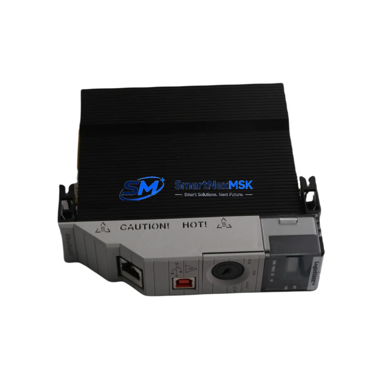
Allen-Bradley 1756-L85E Maintenance-Ready Spare for ControlLogix 5580 Automation
The Allen-Bradley 1756-L85E is a high-performance ControlLogix 5580 series programmable logic controller designed for mission-critical industrial automation environments. As a maintenance-ready original spare, the 1756-L85E is engineered to deliver immediate drop-in replacement capability for aging or failed controller modules in continuous process, discrete manufacturing, and hybrid automation systems. With 40MB of user memory and native EtherNet/IP connectivity, this controller supports complex ladder logic, function block, and structured text programs without requiring firmware re-engineering or I/O reconfiguration.
For maintenance engineers managing aging ControlLogix installations, unplanned controller failure represents one of the highest-risk downtime events on the plant floor. Stocking a verified 1756-L85E spare eliminates the lead-time gap that typically extends emergency shutdowns from hours into days. Each unit supplied by SMARTNEXMSK is function-tested prior to dispatch, ships with original firmware, and is covered by a 12-month replacement warranty — giving procurement engineers the confidence to commit to long-term spare parts strategies without sacrificing budget control.
Spare Maintenance Table
| Parameter | Specification |
|---|---|
| Part Number / SKU | 1756-L85E |
| Series | ControlLogix 5580 |
| Brand | Allen-Bradley (Rockwell Automation) |
| User Memory | 40 MB |
| Communication Port | Dual EtherNet/IP (RJ45) |
| I/O Capacity | Up to 128,000 I/O points |
| Backplane Compatibility | 1756 ControlLogix Chassis (4, 7, 10, 13, 17-slot) |
| Power Supply Compatibility | 1756-PA72, 1756-PB72, 1756-PA75, 1756-PB75 |
| Operating Temperature | 0°C to 60°C (32°F to 140°F) |
| Relative Humidity | 5% to 95% non-condensing |
| Certifications | UL, CE, cUL, ATEX (Zone 2) |
| Firmware | Studio 5000 Logix Designer compatible |
| Replacement Compatibility | 1756-L82E, 1756-L83E, 1756-L84E (same chassis) |
| Country of Origin | United States |
| Condition | Original / New Surplus / Tested |
| Warranty | 12 Months — Replacement Guarantee |
| Pre-shipment Testing | Function-tested, firmware verified |
| Lead Time | In-stock — ships within 1–3 business days |
Maintenance Planning for Continuous Operation
A 1756-L85E replacement should never be treated as an isolated swap. Experienced maintenance engineers know that controller failure is frequently a symptom of broader electrical stress within the control cabinet. When replacing the 1756-L85E, a structured inspection of the surrounding system is essential to prevent repeat failures and ensure stable recommissioning.
Begin with the 1756-PA72 or 1756-PB72 chassis power supply — voltage ripple or thermal degradation in the PSU is a leading cause of premature controller failure. Verify output voltage under load before installing the replacement controller. Next, inspect the 1756 backplane and chassis for physical damage, corrosion on the backplane connector, or signs of overheating at adjacent module slots.
Review all 1756-EN2T or 1756-EN3TR EtherNet/IP communication modules in the chassis. A faulty communication module can cause the controller to log persistent I/O faults that are misdiagnosed as controller failure. Similarly, inspect 1756-IB16 digital input modules and 1756-OB16E digital output modules for blown output drivers or wiring faults that may have caused upstream fault conditions.
For systems with analog process control loops, check 1756-IF16 analog input modules for signal drift or channel failures that could have triggered controller protective shutdowns. If the system uses 1756-DNB DeviceNet bridge modules or 1756-CN2 ControlNet modules, verify network health and node addressing before restoring the controller to service.
In cabinets with relay output circuits, inspect 1756-OW16I isolated relay output modules for contact wear, particularly on high-cycle actuator control circuits. Terminal blocks and wiring ferrules on the I/O wiring side should be checked for loose connections that may have caused intermittent faults. Finally, if the system includes a PanelView Plus 7 HMI communicating over EtherNet/IP, verify that the HMI tag database and communication path are intact after the controller replacement to avoid operator interface alarms on startup.
Maintaining a documented spare parts list that includes the 1756-L85E alongside its associated power supply, communication modules, and key I/O modules is the most effective strategy for minimizing mean time to repair (MTTR) in ControlLogix-based automation systems.
Site Replacement Workflow
Step 1 — Pre-replacement backup: Using Studio 5000 Logix Designer, upload and save the current controller program, including all tag databases, motion configurations, and produced/consumed tag relationships. Store the backup on a secure engineering workstation and a secondary offline location.
Step 2 — Safe de-energization: Follow site LOTO (Lockout/Tagout) procedures. De-energize the 1756 chassis via the main disconnect. Allow the chassis power supply capacitors to discharge for a minimum of 30 seconds before opening the cabinet door.
Step 3 — Module extraction: Press the top and bottom locking tabs on the 1756-L85E and slide the module straight out of the chassis slot. Avoid touching the backplane connector pins. Note the slot position for reinstallation of the replacement unit.
Step 4 — Replacement installation: Insert the new 1756-L85E into the same chassis slot. Ensure the module seats fully against the backplane and the locking tabs engage. Re-energize the chassis and confirm the controller status LED cycles through the normal startup sequence (flashing green → solid green).
Step 5 — Program restore and verification: Download the saved program from Studio 5000 Logix Designer. Verify all I/O modules are recognized, all EtherNet/IP connections are established, and no major or minor faults are present in the controller fault log. Perform a controlled test cycle before returning the system to production.
This workflow supports direct replacement of earlier ControlLogix 5580 variants including the 1756-L82E, 1756-L83E, and 1756-L84E without chassis or wiring modifications, significantly reducing downtime compared to cross-family migrations.
Spare Parts Support FAQ
Q1: Is the 1756-L85E supplied by SMARTNEXMSK an original Allen-Bradley unit?
Yes. All 1756-L85E units are sourced as original Allen-Bradley / Rockwell Automation product. Each unit undergoes pre-shipment functional testing and firmware verification. A 12-month replacement warranty is included with every order.
Q2: Can the 1756-L85E replace a 1756-L83E or 1756-L84E in the same chassis without hardware changes?
Yes. The 1756-L85E is form-factor compatible with all ControlLogix 5580 series controllers and installs into any standard 1756 chassis slot. The program can be downloaded directly from Studio 5000 without modification. Note that the 1756-L85E offers higher memory capacity, which is backward compatible with programs written for lower-memory variants.
Q3: What is the recommended spare parts inventory strategy for ControlLogix 5580 systems?
For critical production lines, maintain at minimum one 1756-L85E controller spare, one compatible chassis power supply (1756-PA72 or 1756-PB72), and one EtherNet/IP communication module (1756-EN2T) per system. For high-availability environments, a cold-standby chassis with pre-loaded program is the industry best practice. SMARTNEXMSK can support long-term supply agreements for multi-site MRO programs.
Q4: How long does shipping take and what documentation is provided?
In-stock units ship within 1–3 business days. Each shipment includes a packing list, test report, and warranty certificate. Export documentation including commercial invoice and country-of-origin declaration is provided for international orders. Contact sales@smartnexmsk.com for expedited shipping options or volume pricing.
© 2026 SMARTNEXMSK. All rights reserved.
Original Source: https://smartnexmsk.com
Contact: sales@smartnexmsk.com | +86 18259474341


