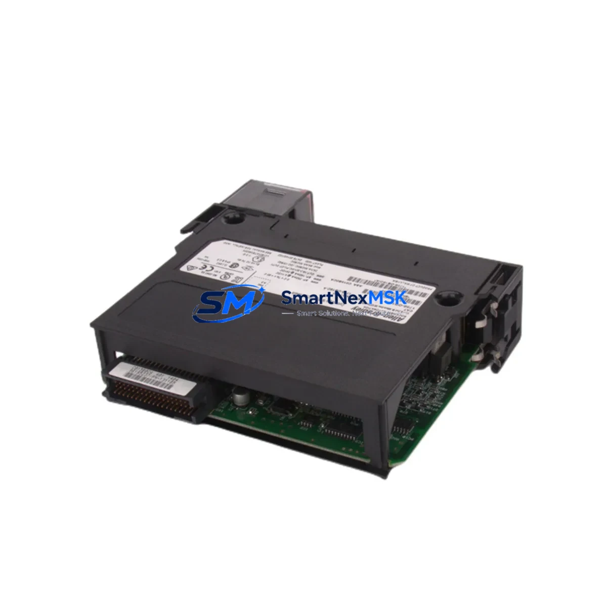
Allen-Bradley 1756-OB16D Maintenance-Ready Spare for ControlLogix Automation
The Allen-Bradley 1756-OB16D is a 16-point, 24VDC sourcing digital output module designed for the ControlLogix 1756 chassis platform. As a maintenance-ready original spare, it is engineered to support rapid field replacement in continuous-process and discrete manufacturing environments where unplanned downtime carries significant operational and financial risk. Whether you are managing a scheduled turnaround, responding to an emergency fault, or building a strategic spare parts inventory for aging ControlLogix systems, the 1756-OB16D delivers the electrical compatibility, diagnostic transparency, and installation confidence that maintenance and procurement engineers demand.
Each unit shipped by SMARTNEXMSK undergoes pre-shipment functional verification, is packaged in anti-static protective materials, and is backed by a 12-month warranty covering manufacturing defects and operational failures under normal industrial service conditions. Long-term supply continuity is maintained for this module, making it a reliable source for both immediate emergency replacement and planned inventory replenishment.
Spare Maintenance Table
| Parameter | Specification |
|---|---|
| SKU / Part Number | 1756-OB16D |
| Brand / Manufacturer | Allen-Bradley (Rockwell Automation) |
| Series | ControlLogix 1756 |
| Module Type | Digital DC Output Module |
| Output Points | 16 Points |
| Output Voltage | 24VDC Sourcing |
| Output Current (per point) | 2A max |
| Backplane Compatibility | 1756 ControlLogix Chassis (all sizes) |
| Isolation | Group isolated, optical isolation between field and backplane |
| Diagnostics | Per-point fault detection, short-circuit protection |
| Operating Temperature | 0°C to 60°C (32°F to 140°F) |
| Relative Humidity | 5% to 95% non-condensing |
| Installation | Hot-swap capable in 1756 chassis with redundant power |
| Origin | USA (Rockwell Automation) |
| Condition | Original Spare — Pre-shipment Tested |
| Warranty | 12 Months from date of shipment |
| Typical Application | Discrete output control: solenoids, motor starters, contactors, indicator lamps |
Maintenance Planning for Continuous Operation
When a 1756-OB16D output module fails or is flagged during a routine control cabinet inspection, the replacement workflow rarely ends with the module itself. Experienced maintenance engineers understand that a single output fault can cascade across interconnected field devices and signal circuits. A thorough site assessment should accompany any 1756-OB16D swap.
Begin by verifying the 1756-PA75 or 1756-PB75 power supply module supplying the chassis — output module faults are frequently caused by power supply degradation rather than the output card itself. Inspect the 1756-A10 or 1756-A17 chassis backplane for signs of corrosion, bent connector pins, or thermal stress that may have contributed to the module failure. If the system uses redundant power, confirm that the 1756-PSCA2 power supply chassis adapter is functioning correctly before re-energizing the replacement module.
On the field wiring side, inspect the 1492-IFM terminal interface modules or equivalent wiring arm assemblies connected to the 1756-OB16D. Loose terminations, corroded screw terminals, or undersized conductors are common root causes of intermittent output faults that are misdiagnosed as module failures. Check the field-side fusing — individual output point fuses or group fuses in the marshalling cabinet — and replace any that show signs of thermal fatigue even if they have not yet opened.
For systems where the 1756-OB16D drives motor starter coils or solenoid valves, inspect the associated surge suppressors and flyback diodes across inductive loads. Failed suppression components can generate voltage spikes that damage output transistors over time. If the control cabinet includes 1756-EN2T or 1756-EN3TR EtherNet/IP communication modules, verify that the network configuration and I/O tree mapping remain intact after the module replacement, particularly if the slot assignment has changed.
In systems with mixed I/O, also review adjacent 1756-IB16 or 1756-IB32 digital input modules for any fault indicators that may have been masked by the output module alarm. Where signal isolation is required between the PLC output and field devices, confirm that any installed signal isolators or relay output modules in the intermediate circuit are operating within specification. Finally, if the system includes a PanelView Plus HMI displaying output status, verify that the tag mapping and alarm configuration reflect the restored module state after replacement.
Site Replacement Workflow
The 1756-OB16D is designed for hot-swap replacement within a powered 1756 chassis, provided the system power supply has sufficient reserve capacity and the chassis supports live insertion. Follow this structured workflow to minimize downtime and ensure system integrity:
Step 1 — Pre-replacement verification: Confirm the replacement 1756-OB16D matches the firmware revision and hardware series of the failed module where possible. Review the RSLogix 5000 or Studio 5000 project file to confirm the module configuration — output point mapping, fault actions, and communication format — before physical installation.
Step 2 — Safe isolation: If hot-swap is not feasible due to safety interlocks or process requirements, de-energize the affected output group using the field-side isolation switch rather than removing chassis power entirely. This preserves the operating state of other modules in the chassis and reduces recovery time.
Step 3 — Physical replacement: Remove the faulty 1756-OB16D by releasing the top and bottom locking tabs and sliding the module straight out. Insert the replacement module firmly until the backplane connector is fully seated and both locking tabs engage. Do not force the module — misalignment will damage the backplane connector.
Step 4 — Configuration restore: If the replacement module is a different hardware revision, use the Studio 5000 inhibit/uninhibit function to re-establish communication. Verify that the controller automatically downloads the stored module configuration. Confirm all 16 output points are reporting correctly in the I/O tree before restoring field power.
Step 5 — Functional test: Energize each output point individually using the controller’s manual output test function and confirm field device response. Document the replacement in the maintenance log, including the date, module serial number, and any associated field wiring findings.
This workflow is applicable to legacy ControlLogix systems running firmware versions 13 through 33 and is compatible with both simplex and redundant controller configurations. Maintaining a minimum of one 1756-OB16D in your on-site spare parts inventory is recommended for any facility operating more than four ControlLogix chassis.
Spare Parts Support FAQ
Q1: Is the 1756-OB16D supplied by SMARTNEXMSK an original Allen-Bradley component?
Yes. All 1756-OB16D units are sourced as original Allen-Bradley spare parts. Each unit is pre-shipment tested for electrical functionality and packaged in anti-static protective materials. A 12-month warranty is provided from the date of shipment, covering manufacturing defects and operational failures under normal industrial service conditions.
Q2: How do I confirm compatibility with my existing ControlLogix chassis before ordering?
The 1756-OB16D is compatible with all standard 1756 ControlLogix chassis sizes (4, 7, 10, 13, and 17 slots). Compatibility is determined by the chassis backplane standard, not the chassis size. Provide your chassis part number, controller firmware version, and Studio 5000 project revision when contacting our technical team for pre-order compatibility confirmation.
Q3: What is the recommended spare parts inventory strategy for the 1756-OB16D?
For facilities operating 1–3 ControlLogix chassis with 1756-OB16D modules installed, maintaining one spare unit on-site is the minimum recommended posture. For larger installations or systems in continuous-process environments where downtime cost exceeds USD 10,000 per hour, a two-unit on-site buffer with a replenishment trigger at one unit is advisable. SMARTNEXMSK supports long-term supply continuity for this module and can fulfill blanket purchase orders for annual inventory programs.
Q4: What does the 12-month warranty cover, and what is the replacement process?
The 12-month warranty covers failures attributable to manufacturing defects or component quality issues under normal operating conditions (within specified voltage, temperature, and humidity ranges). It does not cover damage caused by incorrect installation, overvoltage events, physical impact, or unauthorized modification. To initiate a warranty claim, contact sales@smartnexmsk.com with the order number, module serial number, and a description of the failure symptom. Replacement units are dispatched within 3 business days of claim verification.
© 2026 SMARTNEXMSK. All rights reserved.
Original Source: https://smartnexmsk.com
Contact: sales@smartnexmsk.com | +86 18259474341


